
Thank you gents.
I'll see what I have lying around in terms of components:

Using a second relay to switch the 2K to activate the mute function also means it can sit very close to the TDA7294, which means short leads to the chip, which in turn will hopefully prevent hum.
I took the long leads from the TDA7294, as expected, the loud hum is gone, but the thump is still present upon powering down...
Regards, Jan.
I'll see what I have lying around in terms of components:
- extra relay, check,
- 1N4007 diode, check.
- capacitor polarized 680uF 250V, check, unless it has to be a NP one which I don't have in high values, other than this one from the spare drawer:
Using a second relay to switch the 2K to activate the mute function also means it can sit very close to the TDA7294, which means short leads to the chip, which in turn will hopefully prevent hum.
I took the long leads from the TDA7294, as expected, the loud hum is gone, but the thump is still present upon powering down...
Regards, Jan.
Hi Jan,
What is the relay coil voltage (DC or AC)?
Can you explain or draw a sketch how to wire up the power switch and how to power the relay.
What is the relay coil voltage (DC or AC)?
Can you explain or draw a sketch how to wire up the power switch and how to power the relay.
Hi Chris,
The relay coil is 24V DC.
The power switch only supplies 230V to a 12V AC transformer (its actually 13V due to the raising of the Voltage from 220 to 230V).
This 13V AC gets rectified to 16,3V DC, which powers the relay.
The relay switches the 230V for the soft start module.
The softstart module powers the toroid and the seperate 12-0-12V AC transformer
This seperate transformer powers the low-pass filterboard.
Let me know if I need to make a sketch...
If I understand correctly, I'm adding the diode and capacitor to the relay that powers the softstartmodule.
I also connect the second relay in parallel to the 16,3V DC.
The second relay connects the 2K resistor using the NC pins, activating the mute function when the power is cut by the powerswitch.
The delay provided by the capacitor (polarized or non polarized?) makes the first relay cut the power to the softstart after the mute function is activated.
Regards, Jan.
Hi Jan,
You can use polarized or non-polarized capacitors. If polarized capacitors are used, the positive pin should be connected in between the diode and relay coil. It depends on the relay coil resistance, 680µF may not give enough delay, you can add more capacitors in parallel to increase the capacitance or use a higher coil resistance relay.
BTW, where is the speaker protection board get power from?
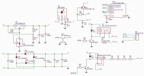
Something like this?

I tried to use Scheme-it, but it I keep getting this in the upper right hand corner:
Initializing application.'
So I used TinyCad instead, took me hours, as I never used a program like this before...
The speaker protection board is powered by the same 12V AC transformer (prior to the rectification), that powers the relays.
Regards, Jan.
I tried to use Scheme-it, but it I keep getting this in the upper right hand corner:
'Scheme-it
The app is loading, please wait.Initializing application.'
So I used TinyCad instead, took me hours, as I never used a program like this before...
The speaker protection board is powered by the same 12V AC transformer (prior to the rectification), that powers the relays.
Regards, Jan.
Last edited:
Speaker protection board added:

I left out the soft start module, as it only delays switching on the toroid.
Getting to grips with such a program is almost as much fun as getting to understand Gerber files for my table top milling machine...
Regards, Jan.
I left out the soft start module, as it only delays switching on the toroid.
Getting to grips with such a program is almost as much fun as getting to understand Gerber files for my table top milling machine...
Regards, Jan.
I would look for digital softstart module, for example an PIC based or Arduino based, its cheaper than 10mF : ) , that way you no need seccond relay or double pole switch, or enything else, easy to integrate and easy to control the things, even you can add ir led to control power off remotely : )
This is how I have solved digital soft start. There is two relays, bottom one is turning first and in next two secconds top one is turned on. Added an ir led which is shared with raspberry pi for the rest of remote control for my audio thing. Power on-off is controled using button or using remote control. Pic microcontroler control power on-off sequence and in the same time handle power on-off from remote control, the rest of remote control is controled by raspberry pi which is an meadia server... For controling "thump" I had, just added one opto transistor to the bottom relay since it is turning first on or off until main relay is turned on-off, that way I have eliminated any "thump".
This is how I have solved digital soft start. There is two relays, bottom one is turning first and in next two secconds top one is turned on. Added an ir led which is shared with raspberry pi for the rest of remote control for my audio thing. Power on-off is controled using button or using remote control. Pic microcontroler control power on-off sequence and in the same time handle power on-off from remote control, the rest of remote control is controled by raspberry pi which is an meadia server... For controling "thump" I had, just added one opto transistor to the bottom relay since it is turning first on or off until main relay is turned on-off, that way I have eliminated any "thump".
Attachments
Last edited:
Hi Savan,
I have no experience with PIC based or Arduino based devices, nor do I want to get more involved in programming electronics.
My Radiomaster TX16S gives me all the software headaches I need...
Regards, Jan.
I have no experience with PIC based or Arduino based devices, nor do I want to get more involved in programming electronics.
My Radiomaster TX16S gives me all the software headaches I need...
Regards, Jan.
Hi, Jan,
I don't see any fuses on your schematic, my suggestion is to at least add a mains fuse after the IEC socket.
I don't see any fuses on your schematic, my suggestion is to at least add a mains fuse after the IEC socket.
I must admit I'm a bit baffled...
I added the diode and a 2200uF capacitor, also the second relay which switches the 2K over the 10uF on the TDA7294 board.
Before powering up, I tested the set-up and the mains relay does switch off after the second relay shorts the 10uF on the board; promising...
Connected everything for the umptied time and powered up the test rig; sound, so far so good.
Without a music signal present, there's a slight hum, but I'll have to turn the volume to 100% to hear it really well, it isn't audible when the music plays. I kept the wiring to the relay, including the 2K, as short as possible.
Now for the big finale...
When I cut the power with the switch which basically only powers the first relay, I get a big 'thud' over all speakers, not just the subwoofer, but also the stereo speakers.
This must be from the 12V transformer which powers the first relay, as the relay itself drops off after about two seconds, powering down the rest of the set-up.
Now what?
What if I use the second relay, which now connects the 2K over the 10uF, to cut the speaker lead to the connectors?
Either directly, putting a second relay in the path of the speaker output, or by cutting the trace of the speaker protection board that powers the relays on the speaker protecion board.
Your thoughts please.
Regards, Jan.
Last edited:
Weird, when the amp has been powered up for half an hour, I have no switching off thud.
I'm going to try this a few times to confirm if the duration of being powered up is a factor...
Regards, Jan.
I'm going to try this a few times to confirm if the duration of being powered up is a factor...
Regards, Jan.
Hi Jan, why don't you try modification from post 49? I think you have a problem with voltages on those stdby functions, and also you don't use the mute function. You are doing 2k resistor mod on stdby function and that way when your power supply is 12V you still have 1V on those pin, please see picture. Even if you use a 40V supply you have 3.3V on those pins. Thats almost on border to not function corectly, threshold voltage is 1.5V for stdby=ON and 3.5V is for stdby=OFF, those small voltage you have (in case 12V supply) is 1V and maybe that cause problem you have right now ( one time work and second time not work).
But I think if you do complete mod from post 49 it might finally work because that way you will have 0V on both mute and stdby! Both functions will be done simultaneously! Post 49 I done by looking into the datasheet of the TDA.
But I think if you do complete mod from post 49 it might finally work because that way you will have 0V on both mute and stdby! Both functions will be done simultaneously! Post 49 I done by looking into the datasheet of the TDA.
Attachments

Last edited:
Well that turned out to be an illusion; no matter how long, or short, the amp is powered up, there's always a hefty 'thud' when cutting the powerWeird, when the amp has been powered up for half an hour, I have no switching off thud.
I'm going to try this a few times to confirm if the duration of being powered up is a factor...
Regards, Jan.
Hi Savan,
When I measure accross the two wires that bridge the 10uF, on the relay, I measure 12,22V DC...
As the current wiring from #67 is relatively simple and doesn't include cutting traces, I wanted to try that option first, this is obviously not the way, so I'll give your solution a try tomorrow.
I can use the extra relay as the switch you show in post#49, right?
Regards, Jan.
Last edited:
Hi Jan,
Sorry for the late reply, I"m with @savan go for the mod on post #49.
If you want to do the mod without cutting traces, here's my suggestion:
Please refer to the amp PCB, those red traces are on the back side.

Remove the 1N4148 diode and the two resistors (33k and 22k) next to it (circled in blue), mount them on a small circuit board and connect it with short wires to the amp board, use a SPDT switch with NC contact connect to ground.
If switch it to NO position can power up the amp and switch it back to NC position can put the amp back to standby/mute, then try the second relay mod and see if it still works.
The reason for grounding the NC is to drain the current of the two 10µF capacitors when the amplifier is in mute/standby mode (like the schematic in datasheet: Figure 18 - High efficiency application circuit).

https://www.digikey.com/htmldatasheets/production/555092/0/0/1/tda7294.html
@savan, what is your opinion?
Sorry for the late reply, I"m with @savan go for the mod on post #49.
If you want to do the mod without cutting traces, here's my suggestion:
Please refer to the amp PCB, those red traces are on the back side.
Remove the 1N4148 diode and the two resistors (33k and 22k) next to it (circled in blue), mount them on a small circuit board and connect it with short wires to the amp board, use a SPDT switch with NC contact connect to ground.
If switch it to NO position can power up the amp and switch it back to NC position can put the amp back to standby/mute, then try the second relay mod and see if it still works.
The reason for grounding the NC is to drain the current of the two 10µF capacitors when the amplifier is in mute/standby mode (like the schematic in datasheet: Figure 18 - High efficiency application circuit).
https://www.digikey.com/htmldatasheets/production/555092/0/0/1/tda7294.html
@savan, what is your opinion?
Something you can try:Now for the big finale...
When I cut the power with the switch which basically only powers the first relay, I get a big 'thud' over all speakers, not just the subwoofer, but also the stereo speakers.
This must be from the 12V transformer which powers the first relay, as the relay itself drops off after about two seconds, powering down the rest of the set-up.
1. Add a 0.01 to 0.047µF 600V film capacitor across the power switch contacts. Even if it doesn't help, it won't do any harm to the setup.
2. Use a µPC 1237 base speaker protection board instead. Usually it can disconnect speaker instantly when power off.
3. Test if any DC voltage at speaker terminals, I doubt it but it's good to know.
- Home
- Amplifiers
- Chip Amps
- Muting TDA7294