 Moved to Chip Amps.
Most peculiar; when I open the switch that Chris suggested in post #5 and power up the amp, there's no sound.
When I close it, the amp plays, as was to be expected.
But, when I open the switch while the amp plays, this make no difference, the music continues regardless of the position of the switch.
Needless to say the switching off 'thump' is also present when I cut the power to the amp.
Using a seperate relay to do the switching is pointless, if cutting the connection does not mute the amp
I did try using the extra relay on the speaker protection board, but this seems to trigger the DC detection and the relays are not switched on, hence no sound. The speaker protection board is fiercly particular about what is connected to it, it seems...
Regards, Jan.
Last edited:
Hi Jan,
It looks like the mute/standby is a latch circuit, once turned on, it stays on until the amp is powered down.
Jan, if you don't mind, you could try grounding the mute/standby circuit with a SPDT switch and see if that mutes the amp while playing. (Please note that the switch is moved in front of the 22K resistor).
Last edited:
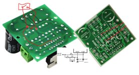
I think you have doing that wrong! Please see picture! Mute + stdby circuit on those small board is allready suplied by VCC, that mean mute+stdby is OFF all the time, reason why mute not work for Jan. You just need to cut wire and add switch between! Also one jumper wire.
Attachments
Last edited:
I've not seen/read the previous two post prior to writing the post below...
Right, putting everything back in place (it still works!), soldered some wires onto pins 9 and 10.
I took the components from this schematic:

And soldered them onto a piece of experimenting board.

I know where mute and standby should be connected to, but which Voltage do I use to power it and where does that come from?
Options are:
1) 30V from the main toroid (too much I gather: 40V after rectification)
2) 12V from the transformer that powers the relay for the power to the softstart (17V after rectification) and delivers 13V AC to the speaker protection board.
3) seperate new powersource.
Regards, Jan.
Right, putting everything back in place (it still works!), soldered some wires onto pins 9 and 10.
I took the components from this schematic:
And soldered them onto a piece of experimenting board.
I know where mute and standby should be connected to, but which Voltage do I use to power it and where does that come from?
Options are:
1) 30V from the main toroid (too much I gather: 40V after rectification)
2) 12V from the transformer that powers the relay for the power to the softstart (17V after rectification) and delivers 13V AC to the speaker protection board.
3) seperate new powersource.
Regards, Jan.
Last edited:
Jan +-40V is a max voltage for TDA, consider lowering them somehow, you are on the verge of burning out your TDA with so much voltage! See picture from post 25 in relation to mute+stdby, it will work if you cut pcb trace as like on picture and add one jumper vire.
Resistors values for mute+stdby is ok, its designed per datasheet and that ok. Its designed to be connected to +supply, so max +40V on mute+stdby trought those resistors and diode is ok. Mute+stdby is allready connected to +supply on main pcb, that mean you can't get mute+stdby ON because its connected to +supply! Option is to cut pcb trace and add one jumper vire as per my picture and all will work!
Resistors values for mute+stdby is ok, its designed per datasheet and that ok. Its designed to be connected to +supply, so max +40V on mute+stdby trought those resistors and diode is ok. Mute+stdby is allready connected to +supply on main pcb, that mean you can't get mute+stdby ON because its connected to +supply! Option is to cut pcb trace and add one jumper vire as per my picture and all will work!
Last edited:
Hi Savan,
You're saying I should use the main toroid as powersupply for the mute/standby circuit, but lower it
by a stepdown circuit?
To which Voltage?
Reason I ask, is I can simply add an extra secundary winding to the toroid to get any Voltage required.
Will that work too?
Regards, Jan.
You're saying I should use the main toroid as powersupply for the mute/standby circuit, but lower it
by a stepdown circuit?
To which Voltage?
Reason I ask, is I can simply add an extra secundary winding to the toroid to get any Voltage required.
Will that work too?
Regards, Jan.
Jan no! You say you have measured +-40V from mains rectification? You are on the verge of burning out your TDA with so much voltage!
+-40V is the max voltage you can supply! Speaking about mains for whole pcb.
Now speaking about mute+stdby, you no need external mute and stdby resisors! Those components is allready soldered on your pcb! But its connected allready to +supply internaly on pcb! And that mean your mute_stdby is by default OFF! Thats reason why your mute+stdby is not working. What you need to do is just do it like on picture from post 25 and everything will work.
Last edited:
Don't panic!
With the current Voltage on our mains, the toroid puts out 31,5 -0-31,5V AC into the TDA 7294 board.
It has played like this for a couple of weeks now, powering an 8 Ohm 100W subwoofer and the temperature on the heatsink has never risen byond 35°C.
Since I bolted on the large heatsink you see in the latest pictures, the heatsink has not gotten over 27°C...
Regarding the mods to get the muting function to work: why are the schematics, I followed to make the board I showed, on the datasheet?
With the purpose to confuse people like me?
Regards, Jan.
Hm google translate seems doesn't translate properly so we don't understand each other. Mute & stdby resistors and diode circuity from datasheet is allready included on your pcb and you no need to create your own that part of circuity. But since those circuity is allready connected to +VCC your mute and stdby is by default OFF. What you need to do now is to cut pcb trace which connects mute and stdby resistors to +VCC. And also after you cut trace you will need one jumper wire from + of the condenser to the TDA. Switch should be connected in place where trace is cut. I combined three pictures to make it clear! See picture

My intention was to help regardless of the bad google translator, my hope I helped.
My intention was to help regardless of the bad google translator, my hope I helped.
Last edited:
Hi Savan,
I slowly start to understand why you and Chris are pointing me towards modifications on the board itself.
Everything is already present on the PCB, exept for some solder pads with wire bridges for the customer to remove, if he wants to use the mute function.
I have two more TDA7294 boards and I'll use those to do the mods you suggest.
This will be a good opportunity to see which of your mods are the easiest to realize and how well they work.
As both mods require an extra switch, I'll use a double pole one, which allows me to combine switching the mains (via relay) and the mute function on one switch (so my wife and kids can also operate the amp once it has been properly built up inside a metal housing).
Regards, Jan.
Hi savan,I think you have doing that wrong! Please see picture! Mute + stdby circuit on those small board is allready suplied by VCC, that mean mute+stdby is OFF all the time, reason why mute not work for Jan. You just need to cut wire and add switch between! Also one jumper wire.
Your method is the same as post #5, break the PCB trace instead of lifting the 22K resistor.
I think the mute/standby circuit utilized SCR for switching, it acts like a latching relay, once the gate triggered to switch on, it stays on until the amp is powered down.
In some circuits, grounding the gate can turn off the SCR, therefore I suggested post #24 @pompebled to try a SPDT switch and see if that can mutes the amp while playing.
If grounding the gate cannot mute the amplifier, another way to try is break pin #1 PCB trace from the ground, and add a switch to pin#1 and ground. The switch should be closed when the amp is powered on and the switch in open position, it will mutes the amp.
BTW, add a switch to pin #1 and ground, the other switch will no longer required, the 22K resistor should go back to its original position.
Last edited:
Hi savan and Jan,Hm google translate seems doesn't translate properly so we don't understand each other. Mute & stdby resistors and diode circuity from datasheet is allready included on your pcb and you no need to create your own that part of circuity. But since those circuity is allready connected to +VCC your mute and stdby is by default OFF. What you need to do now is to cut pcb trace which connects mute and stdby resistors to +VCC. And also after you cut trace you will need one jumper wire from + of the condenser to the TDA. Switch should be connected in place where trace is cut. I combined three pictures to make it clear! See picture
My intention was to help regardless of the bad google translator, my hope I helped.
After I study the images again, lifting the 22K resistor and add a switch (post #5 & 24) only can control the standby function, mute circuit still connected to V+.
savan, I agree your method is correct! However, the trace on pin #7 also needs to be cut to disconnect the mute circuit from V+.
Jan, please try the above modification first. If you have a SPDT switch on hand, use it and connect the NC contact to ground (Blue wire).Hope this makes it work!
Above image is copy from TDA7294 datasheet Figure 20 - High efficiency application circuit.
Last edited:
I found a ten year old thread about TDA7294 Mute/Stdby problem:
https://www.diyaudio.com/community/threads/tda7294-mute-stdby.234126/
The solution is add a 2KΩ resistor across the capacitor in mute circuit.

https://www.diyaudio.com/community/threads/tda7294-mute-stdby.234126/
The solution is add a 2KΩ resistor across the capacitor in mute circuit.
Hi Chris,
I read the old thread and I'm not sure what adding a 2K resistor actually does?
Sure I can add the resistor, but what will happen upon powering up?
It's a long way from adding a switch and cutting traces...
Regards, Jan.
I read the old thread and I'm not sure what adding a 2K resistor actually does?
Sure I can add the resistor, but what will happen upon powering up?
It's a long way from adding a switch and cutting traces...
Regards, Jan.
Thats wrong! That way you will get short circuit (VCC to gnd)!!! Seccond cut is wrong too, those trace must exist, its VCC trace to TDA! I added jumper wire for that after we cut VCC trace for mute & stdby
Jan, please try the above modification first. If you have a SPDT switch on hand, use it and connect the NC contact to ground (Blue wire).Hope this makes it work!
Opps! I was lazy and use your existing drawing, my bad! The two red wire should switch place.
Sorry I'm at work without a computer. Please look carefully if you don't cut the second trace, the mute circuit will still connected to v+.
Sorry I'm at work without a computer. Please look carefully if you don't cut the second trace, the mute circuit will still connected to v+.
No, please take a look at pinout from picture! The corect way is from picture! The green pcb from the right is allready rotated, just folow pinout and traces. If you cut pin 7 than TDA will be without +Vs pin 7! But if you cut as like on picture mute and stdby will be disconnected from +Vs but TDA will be also disconnected, so must be added jumper wire from +Vs (capacitor +) to the pin 7 of the TDA otherwise TDA will not have +supply voltage!
Attachments
Last edited:
There is one bug on pcb (10k resistor and 33k resistor), their places were swapped so that the diode is in parallel with 33k but connected to+Vs instead of 10k connection to +Vs, but ok it can be like that without any problem (RC network is the same = 10k+33k with capacitor 10uF to ground). Mute and stdby on pcb is identic to figure 17 from datasheet (schematic at the botton of picture)
Last edited:
- Home
- Amplifiers
- Chip Amps
- Muting TDA7294