Thanks Savan,
Obviously I have no clue how to work with the calculator...
I'll start combining resistors to get as close as possible to those values.
Regards, Jan.
Obviously I have no clue how to work with the calculator...
I'll start combining resistors to get as close as possible to those values.
Regards, Jan.
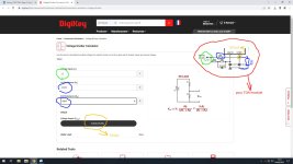
This picture help? This is calculated resistor divider for STBY. You can see that calculated R2 value is 16K, so replace 3.3k from my mod with 16k. Or if you do not have exact 16k calculate yourself for Vout between 4 to 6V is ok too. Now you can calculate yourself for mute, you have 10k+33k=43k in series on your pcb, so for R1 type 43000, for R2 type anything until you get 5Vout, thats all. When you get close to 5V, that resistor R2 value you caclulated is to replace 6.2k from my mod. Its not important to get excatly 5V but between 4V to 6V is ok too! Based on resistor values you have at your home. Important is having not less than 4V on booth mute or stby.
Attachments
Last edited:
Update: I can at least replicate those values in the calculator, so there is progress...
The closest I can get by combining resistores is 30,8K and 15,8K. When I enter these values in the calculator, I get about 5V.
Soldering the resistor 'clusters' onto the bottom of the board is a bit tight, but I managed to avoid shorting anything out, as the amp is currently playing again.
The switching off 'thump' is stil present, I'll add a switch as shown by Chris in #84, to see if the small 12V AC transformer is the culprit...
I just tried simply pulling the 230V lead out of it's socket, switching off is silent, so it's definitely the small transformer that's causung the switching off noise.
I'm thinking of removing the relay that powers the rest of the amp and use the mains switch as a double pole switch to power the soft start.
Regards, Jan.
Last edited:
Hm seems mute & stby funcion is not what tell datasheet. There sould be thump free but seems not a true. or probably much biger power off delay is need after mute&stby is fully on, looks like delay is too short. I realy have no idea right now. Did you measured voltage between gnd and mute pin and also between gnd and stby pin while mute=off, you need to have there close to what you had in calculator so around +-1V close to 5V . Did you replaced two 10uF with two 100nF ?
Jan which DC protect board you have using? I can take a look if you tell me that
Jan which DC protect board you have using? I can take a look if you tell me that
Last edited:
Hi Savan,
On pin 9, I measure 9V, I dare not reach for pin 10 with my probe, as touching the neighboring pins is more than a risk...
9V is a bit much, isn't it?
Regards, Jan.
On pin 9, I measure 9V, I dare not reach for pin 10 with my probe, as touching the neighboring pins is more than a risk...
9V is a bit much, isn't it?
Regards, Jan.
Even 9V is ok! But strange, seems you have more than 12V on input e.g. after rectification you have 21.7V? Just simply measure and replace 12V in calculator with real voltage, you will need to get close to 9V you measured.
Hi Savan,
When I measure on, or rather under the board, on the outside pins of the rectifier, I measure 33V DC.
So I'd have to calculate with 16,5V?
Regards, Jan.
When I measure on, or rather under the board, on the outside pins of the rectifier, I measure 33V DC.
So I'd have to calculate with 16,5V?
Regards, Jan.
Right...
I took the relay, that initially switched on the softstart, from the set-up and used the switch in it's double pole capacity to switch the mains to the softstart.
Now when I switch the power off, there's no thump! So the 12V transformer caused the switching off noise...
I forgot to show the speaker protection board: https://nl.aliexpress.com/item/1005...8893ee4e3!12000029072712022!rec!NL!161642597!
But, if the mute/standby on the TDA7294 works as it should, I should not have to use the speaker protection board.
That is something I'll test tomorrow, by bridging the relay on the SPB.
Regards, Jan.
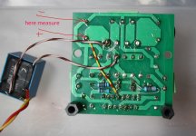
Jan measure at one of the big capacitors, see picture. So those masured value you need to use with calculator. About dc protect I would use them! it help save speakers in case some day something get wrong with apliifier and you get DC voltage on speakers.
Edit: try swap 12V AC input wires on SPB
Edit: try swap 12V AC input wires on SPB
Attachments
Last edited:
Hi Savan,
I can't reach the point you show, but I can reach the same poit on the other side of the board and the common ground : 16V DC.
Feeding that into the calculator gives 22K and the 16K you already predicted
What would swapping the 12V AC on the SPB do?
That's for tomorrow (watching a re-run of Hitchhikers guide to the Galaxy).
Regards. Jan.
As you say 9V is OK to operate the mute/standby function, is there any point in reducing the resistor value to get the actual measured Voltage closer to 5-6V?
Lowering the 16K to 6,8K in the calculator drops the Voltage by 3V, which should be on the mark...
If I have absolutely nothing to do, I may just give that a try, but, if you say it won't do any harm, I'll save that for the time being for when the TDA7293 arrive and I can replace the humming one and experiment with a higher Voltage on the power supply.
Regards, Jan.
TDA can accept rail voltage on mute and stby so 9V or even 39V is ok there! Resistor divider is added because something is needed to discharge capacitors and we need that fast so we used here the minimal voltage and minimal voltage for mute and stby is 3.5V, I would make them 4V minimal in our case 5V is the best, the same time replaced 10uF capacitor with 100nF no need to be e.g. 50V capable but 10V for example becaue of voltage divider. For example if you have 39V on mute and stby your capacitors need to be minimum 50V capable. But if you make 5V using resistors divider you should use 10V capacitors there with no problem. Even you can omit resistor divider in case you have a way to discharge capacitors to gnd.
Swapping AC wires forget it
Swapping AC wires forget it
Last edited:
When switching on the TDA7294 this morning, I noticed a slight hum, increasing the volume on the low-pass filterboard to maximum made it more audible.
I measure 2,8mV over the outer pins of the volume potentiometer and 1,6mV over the speaker terminals.
I'll swap the filter board, to see if that is the source of the hum; first by a brand new one that arrived this week, if that doesn't help, another layout/type of filter board.
Bridging the relay on the speaker protection board, followed by switching off the amp; no thud, so the mute/standby function works!
The 100nF capacitors are rated 100V, so no issues there.
Regards, Jan.

The journey continues...
I wired another TDA7294 using a 2 x 12V 225VA toroid. The filterboard, powered by a buck down module, is much smaller, due to the restrictions of the housing it has to fit in, see picture:

This TDA board has not been modified and switches off without any noise, so the mute/standby works on this one...
Switching on is another matter; this produces a loud 'thud'. I'll have to look into that and find out it's the toroid settling, or the buck down module.
Due to the small housing, I'd rather avoid adding another transformer and rectifier, to power the filter board, adding an extra secundairy winding to the toroid with a rectifier board is also an option.
Your thoughts please.
Regards, Jan.
I wired another TDA7294 using a 2 x 12V 225VA toroid. The filterboard, powered by a buck down module, is much smaller, due to the restrictions of the housing it has to fit in, see picture:
This TDA board has not been modified and switches off without any noise, so the mute/standby works on this one...
Switching on is another matter; this produces a loud 'thud'. I'll have to look into that and find out it's the toroid settling, or the buck down module.
Due to the small housing, I'd rather avoid adding another transformer and rectifier, to power the filter board, adding an extra secundairy winding to the toroid with a rectifier board is also an option.
Your thoughts please.
Regards, Jan.
As I suspected, powering up the filterboard causes the thud on the speaker output, regardless where the power comes from; the buck-down module, or as it currently is wired, my regulated powersupply.
Adding a relay board that switches the speakers on with a delay seems to be the solution, exactly what I tried to avoid, given the small cabinet it all has to fit in...
Regards, Jan.
Adding a relay board that switches the speakers on with a delay seems to be the solution, exactly what I tried to avoid, given the small cabinet it all has to fit in...
Regards, Jan.
Hi Chris,
I have a couple of these, but that would still require a seperate power supplywith a rectifier, for which I barely have room, if I want to respect the distance between signal and power wires.
I could use the buck converter (36 x 21 mm), but this one only puts out 1A, I'm not sure if it can handle the relay board and the low-pass filter.
I can always give it a try, tomorrow I'll let you know what happens.
Regards, Jan.
Having the filterboard and the delay board share a power supply doesn't seem to work, I managed to render another filterboard inoperable, trying it...
I installed my last working filterboard and will order another buck-down board to power the delay board, or add an extra secundary winding plus rectifier, to power it.
Regards, Jan.
I installed my last working filterboard and will order another buck-down board to power the delay board, or add an extra secundary winding plus rectifier, to power it.
Regards, Jan.
Hi Jan,
This mono uPC1273 board mounts directly to a binding post and has built-in rectifier and voltage regulator that accepts 12-18VAC power provides a 3 second delay and DC protection.

UPC1237 LM7812 AC12V-18V Speaker Protection Assembled Board
This mono uPC1273 board mounts directly to a binding post and has built-in rectifier and voltage regulator that accepts 12-18VAC power provides a 3 second delay and DC protection.
UPC1237 LM7812 AC12V-18V Speaker Protection Assembled Board
Hi Chris,
I have one of these board in my spare drawer, it is brandnew and when I apply power, the relay acts immediately, no delay, no matter which way I turn the adjustable potentiometer, nice a dud...
The mono speaker protection boards you show, are a bit to bulky in the small aluminum housing, I have to work with on this project. They are the fast reacting types though, aren't they?
Regards, Jan.
- Home
- Amplifiers
- Chip Amps
- Muting TDA7294