You gentlemen are doing a fine job at driving me crazy...
At the moment I'm not going to cut traces and add a switch, before I have a clear and undisputed schematic of which wire should go where.
Regards, Jan.
At the moment I'm not going to cut traces and add a switch, before I have a clear and undisputed schematic of which wire should go where.
Regards, Jan.
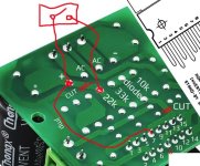
This is what you need to do (two cuts and one jumper wire from the positive pin of the capacitor to the pin7 of the TDA). So pin7 and pin13 of the TDA must remain connected to +Vs, (jumper wire), and mute & stdby circuity removed from +Vs (two cuts). Switch goes paralel at top cut. Thats all.
Attachments
Last edited:
Right. So that's my next course of action, using one of the spare boards I have at hand.
I assume the switch can be a double pole one? One halve for the mute/unmute action and the other halve to switch the relay that powers up the amp.
I'm a bit busy the next few days, so it may be a while before I get to it.
I'll keep you posted.
Regards, Jan.
I assume the switch can be a double pole one? One halve for the mute/unmute action and the other halve to switch the relay that powers up the amp.
I'm a bit busy the next few days, so it may be a while before I get to it.
I'll keep you posted.
Regards, Jan.
Hi Jan,
In the past few days, I have searched the information of the TDA7294 mute/standby function on the Internet and found the following:
On TDA7294 datasheet by STMicroelectronics chapter 9.3
This means that if the mute/standby function is functioning properly, there should be no "thump" or any type of uncontrolled audible transient on the connected speakers when the amplifier is turned on and off.
Since this chip has been out for more than two decades, some DIYers have encountered similar problems with the mute/standby function, and I think we should learn from them first and see how they solved this problem.
I found this thread, the solution is add a 2KΩ resistor across the capacitor in mute circuit.
Savan also recommended this in post #15:

I hope @Sangram sees this thread and gives us his insight.
In the past few days, I have searched the information of the TDA7294 mute/standby function on the Internet and found the following:
On TDA7294 datasheet by STMicroelectronics chapter 9.3
The circuits dedicated to the switching on and off of the amplifier have been carefully optimized to avoid any kind of uncontrolled audible transient at the output.
This means that if the mute/standby function is functioning properly, there should be no "thump" or any type of uncontrolled audible transient on the connected speakers when the amplifier is turned on and off.
Since this chip has been out for more than two decades, some DIYers have encountered similar problems with the mute/standby function, and I think we should learn from them first and see how they solved this problem.
I found this thread, the solution is add a 2KΩ resistor across the capacitor in mute circuit.
The 2KΩ resistor acts as a voltage divider along with the 20KΩ resistor, dropping V+ and charging the 10µF capacitor in parallel with it, this gives a delay time until the capacitor is fully charged and the supply voltage will trigger the standby pin to turn on the amplifier. The 2KΩ resistor also provides a faster discharge path for the capacitor during power down.I read the old thread and I'm not sure what adding a 2K resistor actually does?
Sure I can add the resistor, but what will happen upon powering up?
Savan also recommended this in post #15:
you need to research that and in case your VCC is high for those pins try add some resistor divider at the input of the mute and stdby!
I hope @Sangram sees this thread and gives us his insight.
Last edited:
Hi Chris,
Adding a 2K resistor is a 'non invasive procedure', so when I have the time, I'll try that first and report back.
I also read the datasheet; and at the start of this adventure, using a single powersupply filterboard (12V DC), I had a massive amount of squeeling noise when I switched off the power.
No speaker protection board yet and the noise appeared to come from the capacitors on the filter board draining. Adding the speaker protection board helped a bit, but as the board reacted too slow, only the last section of noise was cut off.
Changing the filterboard for one with a double power supply (12-0-12V AC) reduced the switching off noises to the 'thump' I still have today, but it also created a loud bump powering up (without the spaeker protection board).
The speaker protection board was re-installed and the power up bump was inaudible.
I'm off to fabricate some covers for the wings and hull of my SIG Riser 100, so I can take the sailplane on holliday next week.
Regards, Jan.
Hi Jan,
as I am currently working on an active speaker using three TDA7294V I stumbled over the mute issue myself. My solution is a circuit with delay (NE555) and a relay connecting "mute" with the positive rail of the amp. The circuit will be fed by a small supply with small cap, so the relay opening will be faster than the main supply of the amps dropping.
When I studied your initial post I noticed you are using a toroid with 30V AC secondary. I would worry for the amp´s life as the 7294 is specified with +-40V DC max! The better choice is the 7293 which survives +-50V ....
regards, Klaus
Last edited:
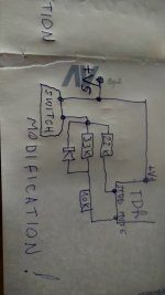
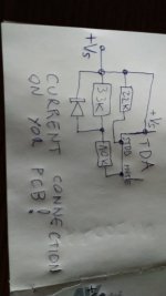
I told him that, it might be higher than +-40V trought rectification. In relation to mute&stdby he should replace 10uF capacitors with for example something like 100nF, but first must try maybe it will no need at all. RC 22k + 10uF is about 0.2 secconds delay which is soo long for getting fast response while turning OFF amplifier trought switch, I would replace capacitors with 100nF. Also I would replace toroid with 24V one, +-40V trought rectification is not a safe for TDA. I would not add 2k I would add 4.7k parallel to booth two 10uF capacitors, one for stdby and one for mute. 2k divider with 22k gives 3.33V which is in the verge of not working properly, see threshold values from datasheet! Mute and stdby is CMOS input, ideal is suplying them with 5V, just calculate divider resistors for 5V and add restistor paralel to capacitor of the booth mute and stdby. If need I can draw all needed modifications on new picture!

Last edited:
This is all modifications I would do:
1. replace torus transformer with one of 24V, trought rectification you are at around 30-35V which is a safe for TDA
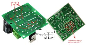
2. replace two 10uF capacitors with 100nF (might be bipolar)
3. two cuts
4. one jumper wire
5. add paralel 3.3k resistor to first capacitor
6. add paralel resistor 6.2k to seccond capacitor
With this modifications mute & stdby will be suplied trought resistor divider with around +5V and booth pins with their capacitors (100 nano rarad) will be fast discharged when you turn OFF switch, so you should not hear "thump".
Yes, you can use two pole switch.
1. replace torus transformer with one of 24V, trought rectification you are at around 30-35V which is a safe for TDA
2. replace two 10uF capacitors with 100nF (might be bipolar)
3. two cuts
4. one jumper wire
5. add paralel 3.3k resistor to first capacitor
6. add paralel resistor 6.2k to seccond capacitor
With this modifications mute & stdby will be suplied trought resistor divider with around +5V and booth pins with their capacitors (100 nano rarad) will be fast discharged when you turn OFF switch, so you should not hear "thump".
Yes, you can use two pole switch.
Attachments
Last edited:
'Him' here,
The amp has been playing at my sons house for weeks, he tends to forget to power down the sub amp, as it sits in a cabinet beneath the TV, so it has most likely been under power for several weeks. The heatsink was a lot smaller during this testrun and never got beyond 35° C.
With the large heatsink, under power for the day, it barely gets 24-25°C.
Despite what the datasheet says, the TDA7294 can handle 42,5 0 42,5V DC, or mine is a misprinted 7293, or I just got lucky.
Time will tell, when I start mods on the other two TDA7294, I have at hand.
I'll start with the 2K from post #45 and see what happens.
Regarding Savan's mods:
1) I have several toroids on the shelve, so giving 24V a try is no problem. These are older toroids (from the 220V era) and deliver more with the European Voltage being slowly raised (and fluctuating, as the load changes), so in stead of 32V, it'll be more like 34,7- 0 - 34,7V DC after rectification, but that's not an issue.
2) Replacing the two capacitors to reduce the response time of the mute/standby function; I should have 100nF lying around.
3) Cutting two traces, no problem.
4) Add a jumper wire from the positive power supply to pin 7 of the chip.
5&6) Add 3,3K and 6,2K resistors in parallel to the replaced capacitors.
7) Use a double pole switch to power the amp and the mute/standby circuit.
I'm having some busy days ahead, so It may be a while before I can work on the mods.
At the moment, the one in the pictures powers the subwoofer in my workshed, so I may assemble the modified set-up on a new piece of plywood.
@Klaus: if the above doesn't produces the desired result (no switching off noise), I may ask you for a schematic and/or pictures of your solution...
Regards, Jan.
Last edited:
Well, that was a bit dissappointing.
Only adding the 2K to the board, mutes the sound permanently, removing it allowed the amp to play.
As a precaution, I replaced the 30-0-30V toroid with a 12-0-12V AC, making the TDA7294 considerably more docile; where previously the volume was below the 9 o'clock position to keep up with the stereo speakers, it's now at the 12 o'clock position, still sufficient for my nearfield listening, with the bandpass sub underneath the desk.
Not sure if it's sufficient power for the living room, where the front speakers are very efficient.
I had soldered the 2K on one of the spare boards, swapping it out for the one that has been working on 30V for weeks without a hitch (now running on 12-0-12V AC).
After switching on the power there was a pop and the amp was dead, no visual damage other than a yello-ish spot on the chip, I had not noticed before.
Bummer...
I swapped the board for the second spare, this time without soldering the 2K on the bottom.
Upon powering up with the 12-0-12V toroid, there was only a loud hum from the sub, no music.
I'll have to take a close look on both boards tomorrow to see it I can find somthing wrong. A short inspection showed a tiny smear of heatconductive paste touching pins 6 trough 8, I washed it off with alcohol and will test tomorrow if this makes any difference.
I may have to order a couple of TDA7294 chips, or 7293, provided these are compatible on this layout, which they should, as the boards are advertized with both versions and look identical.
This is the link to the TDA kit that has ran for weeks on 30V:
https://nl.aliexpress.com/item/4000..._main.478.21ef1802F987Lo&gatewayAdapt=glo2nld
The other two came assembled...
Regards, Jan.
Last edited:
Hi Jan,
Sorry to hear that you burned two amplifier boards. I don't understand why lowering power supply voltages or adding a 2KΩ resistor would cause this, unless some wiring is shorted. Are the layouts of the three PCBs the same?
However, I wonder if those TDA7294 that come with the board have exact specs from STMicroElectronics.
Pin 6 is a bootstrap and pin 8 is a -Vs, might be a reason for burning board if short circuited. Transformer 12-0-12 is a 4 pole or with 3 pole (center tap)? Brum might mean that you have a ground issue, for example on audio input or maybe general gnd issue. Also It is not excluded that the volume control board also suffered, You need to disconnect all sections and plug in section by section to find the cause. Also check for DC voltage on audio output of the volume control board.
Last edited:
I put the TDA 7294 back with which this thread started; other than the lower output, it works as before, so the surrounding components are in good working order.
Instead of soldering the 2K directly onto this board, I used two wires, to be able to connect or disconnect the resistor while the amp is playing. Using a switch, the amp is muted, so when I use a double pole switch, I can cut the power without having a thump!
Making sure no shorts were created is something I took great care of (other than missing the smear of heat conducting paste).
Both toroids, the 30V and 12V, have double secondairies, which can be configured in parallel to have double the Amperage, or wired in series to double the Voltage, or wired so there's a center tap with two times the single Voltage (12-0-12V AC).
Mine are wired in 12-0-12V AC.
I checked, all three board have an identical layout.
I'll do another check on the two 'spare' boards today, using another powersource and filterboard, so I don't have to swap them with the first board that currently drives my subwoofer.
I looked for replacement TDA7293 chips, but found the prices wildly varying, maybe I'll order them 'locally' from Mouser or Farnell.
Regards, Jan.
If you can use the switch to mute the amp while it's playing, I think you've found your solution!Instead of soldering the 2K directly onto this board, I used two wires, to be able to connect or disconnect the resistor while the amp is playing. Using a switch, the amp is muted, so when I use a double pole switch, I can cut the power without having a thump!
Well, sort of...
I swapped the mains switch for a double pole one and wired the 2K to one side and the mains to the other.
I now have an extra issue: the wiring for the 2K resistor to the TDA7294 runs partly parallel to power leads. The amp hums rather loudly...
On top of that, switching off the power still produces a thump, so the double pole switch solution doesn't work, the 2K has to be connecter prior to cutting the mains.
I'll look into that later, now I'm off to watch the F1 sprint race at Spa-Franchorchamps.
Regards, Jan.
0.2 secconds delay with 22k+10uF is a bit long to eliminate thump. Solution with smaler capacitors might help but the best solution is using something like post 13, the ideal thing is having digital softstart module where you can program TDA mute first on one side and on another side delayed mains power off. What happens when you do mute first with 2k resistor and after that power off mains, does then you hear thunp?
Or if you can somehow add analog delay somehow inside soft start power off circuity so that you mute tda first and prolong main power off so that tda have free time to mute first before mains goes off. Which soft start module you have using?
Hi Savan,
I did try that prior to using the double pole switch; connect the 2K, followed by cutting the power.
No thump.
I am indeed trying to find a way to mute the amp via the 2K, before the main power gets cut.
Easiest way is using two seperate switches, but that's a bit cumbersome in practice...
Regards, Jan.

- Home
- Amplifiers
- Chip Amps
- Muting TDA7294