It will be the small things like less that perfect match of the thermal environment or less than ideal connection in the resistor or to the circuit board. When looking at PPM or PPB levels these small difference show up. Many will be transitory. Things like temperature and voltage coefficient are potentially large errors that do mostly cancel out using the network. Thats when the next level of stuff surfaces.
The Radiometer CLT-1 was created to sort out potentially unreliable resistors in a batch of identical resistors looking at the harmonics generated. Mine has an HD3 distortion floor of -170 dB. Good wirewond and metal film resistors can reach that level but there will be zingers in a batch. Will this show in audio? i really doubt it. But I could be surprised.
The Radiometer CLT-1 was created to sort out potentially unreliable resistors in a batch of identical resistors looking at the harmonics generated. Mine has an HD3 distortion floor of -170 dB. Good wirewond and metal film resistors can reach that level but there will be zingers in a batch. Will this show in audio? i really doubt it. But I could be surprised.

Just a few comments: temperature changes are slow processes, may influence overall gain but hardly worsen the here addressed distortion.
Your meter has an astonishing low THD floor, but as long as resistors are equal to a large degree, this distortion don’t have to be that low and will be cancelled in a chain of identical resistors.
For an amp with a gain of 25, a single Rf will see a 24 times larger voltage as Rs, so its voltage coefficient and wattage will have a large impact on Rf and you will need a very high grade resistor when looking for a very low distortion.
With 25 identical low cost 0.25 Watt metal film (SMD) resistors from a decent supplier, you won’t need any expensive high wattage Vishay foils for Rf.
Remaining THD from non ideal connections or PCB layout will be way below the amp's own distortion.
That's my experience.
Hans
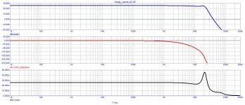
LME49860
Gain 28 dB
output peak voltage 300mV to 3V
THD at 3V -169 dB
Without the coil the sim would always stop


Gain 28 dB
output peak voltage 300mV to 3V
THD at 3V -169 dB
Without the coil the sim would always stop
Last edited:
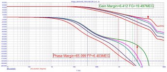
[B]Bernhard[/B], development analysis begins with these two graphs. If there are no stability margins or a group delay greater than 100...120 ns, then it makes no sense to make a layout
Attachments
Last edited:
@petr
sorry
This is a currentfeedback amplifier, what do you think is special ?
As I don‘t have the japanese transistor models, I replaced by BC.
Idle 270 mA
THD @ 1khz / 1W / 8 ohms = -135 dB
My amplifier is exactly 100 dB better.
You fail to understand that your ****test is of no significance because the theoretical, not frequency limited sineburst can not be generated in reality plus the real world audio band is limited to about 40 khz.
You are trying to walk to the moon while fighting windmills.
/sorry
Bernhard,
The APx Burst Waveform Utility generates sine waveforms and then saves and/or loads them into the APx generator. A burst contains a certain number of signal cycles at a full level followed by a period of cycles at a lower level.The transition from high to low is instantaneous at the zero crossing of the waveform. The low level can be set to any level from 0 to 100%. This utility does not create bursts of a certain shape, where the transition from high to low occurs gradually over time.
https://www.ap.com/technical-library/creating-burst-waveforms-in-apx/
I am not Peter.
I asked you to do the same tests for your good amp that I did for mine.
But no, it's not.
Attachments
That‘s great.The APx Burst Waveform Utility generates sine waveforms and then saves and/or loads them into the APx generator.
Let‘s have a closer look at the text
That generator is a 192 kHz DAC.
1/2 sampling frequency = 96 kHz is the highest frequency contained in the spectrum.
As I said.
Sure.I am not Peter.
If it walks like a duck, talks like a duck .... 🙄
I am not Peter.
Let‘s see…
Only 1 post in 2022. No more.
Now after Petr was banned, you pop up with exactly the same nonsense.
Just by coincidence of course.
If it walks like a duck and talks like a duck, it is probably a duck.
Me thinks, Petr is now using inactive friend‘s account.
But you say you are not Petr. Of course not.
👍
Considering the relative uselessness of THD as "figure of merit", I took a look at IMD at my favorite frequencies, 950Hz & 11.5 KHz, equal amplitude. IMD could be estimated at ~-60 dB but it's (very) low order hence the amp is likely to sound rather well (better than those with lower THD but much higher "grass floor"). Lowering IMD is possible (of course) but the question then is, "would it be audible?" as one doesn't design amps to look better in simulators but instead, to sound better.

I don‘t think there is much that can be done here.
Does not look so bad but practically there is some flaw.
The two halfwaves have their own feedback path, if the resistors are not tightly matched, the 2 halfwaves will have a different amplitude and K2 and K3 will rise real quickly.
Only if one of the resistors is off 1% from the other, K2 rises from-120 to -87 dB and K3 from -127 to -117 dB.
More sweet sound if you like that, unpredictable results if you don‘t know.
Two amplifiers built by different people could sound noticeably different.
Even left and right channel could not sound the same.
The word "complementary" in amps is a euphemism, "upper" and "lower" half never are the same, even in sims (look at the onset of clipping in amps using "complementary" mosfets). Selecting components helps but has its limits, NFB is useful too but has its own set of issues. What in CF amps also matters a great deal is input impedance - the sim source usually is set to 0.001 ohm (increase to 1k and see what happens). That suggests the virtual earth topology would have the least issues.
This symmetrical design requires good matching in general, however the mentioned issue was the most obvious and the worst, I not want look more deep into this, for me - case closed.
Yes… but here the feedback network directly determines the output amplitude.The word "complementary" in amps is a euphemism, "upper" and "lower" half never are the same
It is similar to using voltage dependent resistors in the feedback path, like carbon composite,
Last edited:
N and P mos have different saturation properties hence clipping is asymmetric (shows best at virtual earth, see pic)- no amount of feedback could correct that.
It will be most interesting to see the IM your amp produces at maximum output, with 1:1 11.5 KHz and 950 Hz.

It will be most interesting to see the IM your amp produces at maximum output, with 1:1 11.5 KHz and 950 Hz.
Yes, however clipping is outside normal operation conditions.N and P mos have different saturation properties hence clipping is asymmetric
But here the error is directly introduced by the two different feedback paths.
- Home
- Amplifiers
- Solid State
- Musings on amp design... a thread split