I guess assuming 1Hz BW?at 1.1nV-rtHz input noise and 7.746V out, noise level is down at 20log(7,764/1.1nV) = -196dB referred to 7.746 Volt input.
Hans
All resistors will be matched as good as it gets, starting from 0.01% parts.
Can easily find 0,0001% matches in 12 boxes of these.
Just as a example.
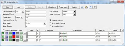
[B]Bernhard[/B]. here are the frequency response (Bode) analysis settings to get three graphs: frequency response, phase response and group delay (Group Delay)
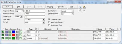
and then these are the Loop-Gain analysis settings. Additionally, it is necessary to add to the Setting the limits for changing the capacitor connected in parallel to the load (I gave an enumeration from 50 nF to 2 uF)then, even without a scheme, you can imagine the level of development
Attachments
The resistor measurements are impressive BUT the Dana 6000 is only good to 20 PPM within 24Hr of calibration. Those parts are pretty small and even 5 PPM/C will quicly show up as the signal across them changes. For a power amp you would need at least a 5W resisotr. My Optimation 10W calibrator amp has a 5W Vishay foil in the feedback to hold tolerance. You need mass to average the heating through an audio cycle to PPM. Even Vishay foils fail at 10 Hz due to the thermal cycle.

And what ohm value ?My Optimation 10W calibrator amp has a 5W Vishay foil in the feedback to hold tolerance.
Those resistors are not for a power amp, or if I would use them, maybe in a ccs.
I think even if that dvm is out of calibration, it is still good for matching. in many cases, absolute values are not so important.
The feedback resistor is 23.01K .01% with a 10 Ohm trimmer in series. There are a lot of details in the design to maintain accuracy including remote sensing (difficult for AC) Low distorton (distortion degrades accuracy), stability in level and gain, etc. If the gain changes in the amp then the accuracy is gone.
Those resistors were made 25 years ago (if I'm reading the date code right). Have you checked them for change/drift? And typically small resistors like those will react to the heat from assembly and change value, often a lot more than .01%, not to mention the effect of humidity, bending leads, etc.
The Dana may be fine for matching but not necessarily for checking tempco to 5 ppm. In the world of linearity below -100 dB there are so many things that can compromise accuracy. The details in a Kelvin Varley bridge to get accuracy are pretty amazing (e.g. solder blobs on wires to tune the resistance) and only for DC. Extend that to AC and its even more challenging.
Fortunately those types of precision are not critical to audio. Its really very forgiving (or the telephone would never have worked).
23k is quiet high I wonder what is the max. voltage across that resistor so that it has to be 5W…The feedback resistor is 23.01K .01% with a 10 Ohm trimmer in series.
In this case its 120V RMS. The amp will deliver 120V RMS from 10 Hz to 1.2 MHz at .01% flatness. Not high current by audio standards but enough, its for calibrating meters. Attached is a poor scan of the schematic. I'm not sure if it helps a lot.
Attachments
The lowest distortion you can get is to use the same value and make for all feedback resistors.
For instance for a gain of 20, use 19 + 1.
Say their resistance is R with deviation d from temp and voltage dependancy, then gain will be 1+(19*(R+d))/(R+d) = 20 while d is completely cancelled, especially the non linear voltage dependent variant causing distortion.
Hans
For instance for a gain of 20, use 19 + 1.
Say their resistance is R with deviation d from temp and voltage dependancy, then gain will be 1+(19*(R+d))/(R+d) = 20 while d is completely cancelled, especially the non linear voltage dependent variant causing distortion.
Hans
Thanks, understand. Max. dissipation 0,6W in Rf = 1/8 rated power.In this case its 120V RMS.
For 25 resistors that means 50 solder joints. Opinions on wether that is good or not, differ. Plus every resistor has two junctions of copper to resistive material.The lowest distortion you can get is to use the same value and make for all feedback resistors.
This may convince you for a 10x Gain amp.
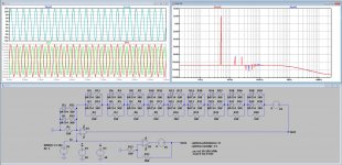
Amp U1 with extreme non linear feedback resistors versus amp U2 with perfect resistors.
Upper left the 5Khz@+/-15V peak output and the differing currents flowing through Rf and at the right their distortion spectra.
Hans
Amp U1 with extreme non linear feedback resistors versus amp U2 with perfect resistors.
Upper left the 5Khz@+/-15V peak output and the differing currents flowing through Rf and at the right their distortion spectra.
Hans
Attachments
It means, the diodes start conducting but errors cancel…?This may convince you for a 10x Gain amp.
I keep that in mind.
Demian, could you please be more specific to which errors don’t track, I think all dominant non linearities will be greatly reduced, the most harmful of them being the non linear voltage coefficient.
I found out the hard way when THD was too high.
The above LTSpice sim nicely confirms this.
Hans
I found out the hard way when THD was too high.
The above LTSpice sim nicely confirms this.
Hans
If we have Rf 25 x 1kohm and 1 kohm shunt, the ratio is 0,04
If each resistor heats up and has 1,01 kohm, Rf becomes 25,25 kohm and the shunt 1,01k ohm, the ratio is still 0,04.
Other effects could be of a more random nature ?
I think instead of so many resistors, I would use a par/ser combination so that the power rating is high enough. If I had that issue.
Also because of cost. 52 Vishay foils for the feedback of a stereo amp ?
Last edited:
- Home
- Amplifiers
- Solid State
- Musings on amp design... a thread split