Hi Jan,
I would like to answer your postings, but that has to wait until tuesday, i’m running out of time now.
Hans
I would like to answer your postings, but that has to wait until tuesday, i’m running out of time now.
Hans
Yeah I was sound asleep when you wrote that 🙂
Unlike electrical batteries, my internal battery is recharged by doing nothing ;-)
Jan
Unlike electrical batteries, my internal battery is recharged by doing nothing ;-)
Jan
Since Petr evaded the confrontation, I made the sims with 3 distortion free first order R-C filters,
Hans
It's just that Petr doesn't deal with such nonsense! 🙂
Here is the result of testing on the second period of an RC-chain with a time constant of 1.25 µs and a real amplifier having the same signal delay time.
Also feel the difference between the second period and the tenth period.
I hope it is clear that it makes no sense to test the RC-chain on the tenth period
Petr
Attachments

Fantastic, enough proof to suggest that you are an overunity being. 🙂Unlike electrical batteries, my internal battery is recharged by doing nothing...
Fantastic pictures, but without explanation what they mean they are just a bunch of lines in nice colors.It's just that Petr doesn't deal with such nonsense! 🙂
Here is the result of testing on the second period of an RC-chain with a time constant of 1.25 µs and a real amplifier having the same signal delay time.
Also feel the difference between the second period and the tenth period.
I hope it is clear that it makes no sense to test the RC-chain on the tenth period
Petr
1) The first and second picture in #1003 have exactly the same subscripts, yet they differ quite a lot.
2) What is your meaning of "second period" and "tenth period".
3) What is R2016_10_Rogov_Thd&Freq_(RL).Circ Freq=10...250K
4) What is shown with Thd(harm(vRL)).freq) (%) are you multiplying Thd with freq and how is this Thd measured, details, details, details.
5) What is High_Y(thd(harm((v(RL)).freq).1) vs freq
Any experiment has no value when it can't be replicated by an independent source.
There is no circuit diagram provided of the amp you used, so even when understanding what you did, your plots can't be verified.
And using just some amp can never be used as a generalization to prove that it can't be compared to a RC network, apart from the fact that this is besides truth.
Last but not least, where are the "speed distortions" that you declared as being amplifier errors, that was the point I declared to be a non issue.
I don't see them in your current simulations so are changing the subject ?
Hans
Fantastic pictures, but without explanation what they mean they are just a bunch of lines in nice colors.
Hans, I have already explained that it is impossible to measure the loss of information on pure sinusoidal signals.
How to measure exactly the losses I showed on numerous examples by the compensation method. I don't know of any other method. Everything was detailed in the article on distortion measurements.
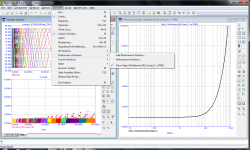
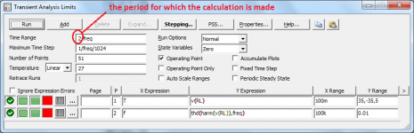
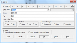
As for plotting the dependence of THD on frequency, this is done by the MicroCap program in a step-by-step mode. The algorithm of work was written by Russian professors of the Smolensk University (the married couple Amelins).
In this case, the generator sequentially operates at frequencies from 250 kHz to 10 Hz, in steps of 0.9. You can set the number of generated sinusoids. In this case, using the example of the Rogov amplifier (Radio 2016-10), I showed the results of the calculation using two and ten sinusoids.
If you are familiar with the algorithm of the simulator, you should know that distortion measurements are carried out on the last period (in one case, on the 2nd period, in the other, on the 10th period).
Attachments
Last edited:
What is your problem ?
It is very normal that amplifier THD is rising above 1 kHz due to well known effects like phase shift.
Just simulate THD vs Power at 10 kHz. Or whatever frequency you want.
So you do not need all that sine burst nonsense, a technically correct sine burst can never reach the amplifier because it is low pass filtered by the preceding audio chain. That´s where your story ends.
Why you ignore ?
May I suggest that you do something constructive ?
Perhaps you present the schematic of a speed amplifier that has a very low THD which is constant from 1 kHz to 20 kHz at least ?
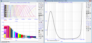
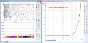
At every step, I am pointed out that a 10 kHz burst has cosmic slew rates, and they even introduced the IN-105, which shows the spectrum of a burst of one period (Fig. 01). True, I don’t quite understand how this period can be assembled from 15 harmonics, the levels of which are highlighted in black bars.
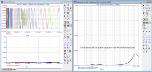
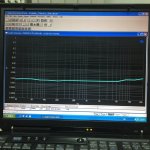
To begin with, let us measure the slew rate of such a signal at the output of a typical amplifier in Fig. 02. As you can see, the signal slew rate does not exceed 2 V/µs.
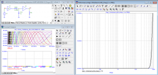
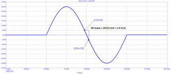
The highest harmonic has a frequency of 1.5 MHz with a level of -40 dB. Maybe this harmonic has a cosmic slew rate? Let's measure, fig. 03. But here, too, the slew rate does not exceed 3 V/µs.
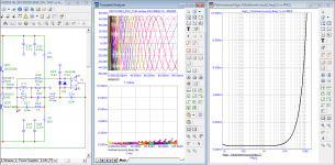
The 13th harmonic has a higher level, fig. 04. But even this single harmonic has a slew rate of only 4 V/µs, which is more than an order of magnitude lower than the slew rate of most typical amplifiers.
Regards
Petr
To begin with, let us measure the slew rate of such a signal at the output of a typical amplifier in Fig. 02. As you can see, the signal slew rate does not exceed 2 V/µs.
The highest harmonic has a frequency of 1.5 MHz with a level of -40 dB. Maybe this harmonic has a cosmic slew rate? Let's measure, fig. 03. But here, too, the slew rate does not exceed 3 V/µs.
The 13th harmonic has a higher level, fig. 04. But even this single harmonic has a slew rate of only 4 V/µs, which is more than an order of magnitude lower than the slew rate of most typical amplifiers.
Regards
Petr
Attachments


My amplifier sim in MC12
@ 20 Hz, 100 HZ, 1k, 5k, 10k, 20k / Vout 10 Vp

10 Wp into 8 ohms THD -230dB 9 zeros... 0,000.000.000.2 % @ 1Wp

@ 20 Hz, 100 HZ, 1k, 5k, 10k, 20k / Vout 10 Vp
10 Wp into 8 ohms THD -230dB 9 zeros... 0,000.000.000.2 % @ 1Wp
LOLAt every step, I am pointed out that a 10 kHz burst has cosmic slew rates
Does your DAC have a cosmic slewrate ? Or does it have a low pass filter on the output ? Does it have a opamp output stage ? A 192 kHz DAC has what bandwith ? Cosmic ?
Do you know that oversampling filters suffer from pre-ringing ?
How do you generate that 10 kHz burst to test your amplifier ? Not in sim. In real world.
Let me guess... No answer. As expected.
Do you think I throw around schematics like candy ?... That was over 10 years of hard work. I will publish it this year, or next, hopefully.
wow, seems really interesting. Can you please show us your model or a principal scheme at least?My amplifier sim in MC12
@ 20 Hz, 100 HZ, 1k, 5k, 10k, 20k / Vout 10 Vp
View attachment 1142680
10 Wp into 8 ohms THD -230dB 9 zeros... 0,000.000.000.2 % @ 1Wp
View attachment 1142682
Why brag about something that no one can check? Give at least the result of test of a real amplifieras dadod did.Do you think I throw around schematics like candy ?... That was over 10 years of hard work. I will publish it this year, or next, hopefully.
Okay, here are the main graphs:
Bode diagram with Group Delay;
Loop gain curve on reactive load 50, 100, 500 nF and 2 uF
since your scheme is so secret
Best regards
Petr
Last edited:
Above was with gain of 28 dB, if I reduce to 20 dB, THD drops below -240 dB at low power, slightly modified circuit too.

Yes, as you say, loop gain drops at some point at rising frequencies, causing phase shifts, a larger feedback signal at the inverting input and less suppression of distortion components.As to the erroneous ideas of feedback 'going round and round' still turning up, despite the efforts of many smarter than me.
Look at the two inputs of the diff pair. One signal is the input, the other comes from the feedback network. Normally the second signal is phase shifted and delayed by the transit time - those are two different things. The phase shift is for audio frequencies much larger than the transit time which can be ignored for now. But there is always a continuous signal at the feedback input to the diff pair - it is not like the diff pair gets an input and then has to wait for the feedback signal!
So what does the diff pair do when presented with two signals? It outputs an amplifed difference between the two. If the feedback signal is a bit smaller than the input, the diff output is higher then when they would be equal. And vice versa. (Assuming correct phase for now). But the feedback is still operating normally, and corrects the nonlinearities.
Now, as frequency rises, the error (difference between input and feedback signal) increases and the non-linearity is less corrected, but during all these conditions the feedback works as it should - but has less correcting power because the loop gain drops and the error rises.
Of course, at some point the freq gets so high that the feedback signal gets towards opposite phase to the input signal, the output of the diff pair increases where it should decrease (and v v), and the system becomes unstable. But - and this is important - it only becomes unstable because the feedback continues to work as it should! The physics are what they are.
Jan
And at the point where the feedback signal´s phase gets shifted 180 degrees and beyond, loop gain should be well under 0dB, if not you will have a nice oscillator.
But when this condition is met, indicated as phase margin, you will have a stable amp despite its largely shifted feedback signal.
Hans
- Home
- Amplifiers
- Solid State
- Musings on amp design... a thread split