It's obvious that petr_ thinks that what happens at startup at zero, happens every time zero is crossed. And he dont understand what happens at start from zero either. This was obvious already many months ago when this was run trough the washing machine. He is stuck in a position that I don't think he will leave. Evar.
//
//
how many dogmatists here who cannot see beyond their noses !!!
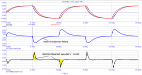
The types of distortion were well described by Jiri Dostal in a book on operational amplifiers and gave examples of how to measure vector distortion by the compensation method.
Hafler's method serves the same purpose. But vector errors indirectly speak about the real level of distortion.
Baksandall showed how to measure real distortion using a delay line.
However, it is not so easy to make a real delay line close to ideal.
There were attempts to bring the phase characteristic of the delay line to the phase characteristic of the amplifier being measured in a number of vector distortion indicators (in particular, they were widely used by the Russian radio amateur I. Akulinichev). But in this case, phase distortions, which are no less important than nonlinear ones, drop out of the analysis.
Therefore, it is best to virtually (where there are no problems with an ideal delay line) to apply exactly the ideal delay line at the tested frequency.
Attachments
You can do all these tests with low-passed square waves, look at the difference between input and output, and show us that there is something we don't know yet.
People can much better relate to things they are familiar with.
Who knows what V(out)+9.88*v(tPD)-75m means?
Jan
People can much better relate to things they are familiar with.
Who knows what V(out)+9.88*v(tPD)-75m means?
Jan
Last edited:
Dear petr_, I suppose you have designed an amp that has none of the problems that you describe. Can you please present the design along with measurements and schemas so that we can see how it looks and maybe build one? After all this is a DIY site!? If you haven't - what is it that you are after - save us from evil? Whats your mission?
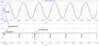
Is it the red trace that has "speed distorsion" - again it looks like x-over distorsion from a poor design and if it is the red trace, it seem to have broken the speed limit and should be fined for that.
//
Is it the red trace that has "speed distorsion" - again it looks like x-over distorsion from a poor design and if it is the red trace, it seem to have broken the speed limit and should be fined for that.
//
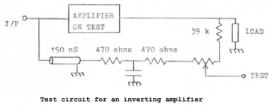
There were no fast amplifiers in Baxandall's time. Therefore, Baksandall used a fixed 150 ns delay line, and the missing delay time was selected using an RC chain.
In this case, the output signal was attenuated to the level of the input signal; as a result of subtraction of the signals, distortions introduced by the amplifier were obtained, weakened by a factor of Ku.
Unlike Baksandall's method, I increase the input signal to the output level by multiplying by Ku. In this case, we immediately get life-size distortions.
In the model, an asterisk (*) is a multiplication sign
In some cases, there is a constant voltage at the amplifier output, which also has to be added / subtracted (depending on the sign) to compensate for the constant component in the output signal.
Attachments
Petr, if I understood you correctly, the amplifier errors that you mention are caused by a transient in the input signal. Like the input that starts from zero, is really a transient, correct?
If this is the case, then if you feed the amp with a square wave (passed through a 30kHz low pass as you used earlier), then we should see those errors at each edge of the square wave. Is that correct?
Jan
If this is the case, then if you feed the amp with a square wave (passed through a 30kHz low pass as you used earlier), then we should see those errors at each edge of the square wave. Is that correct?
Jan
In post #493 you test your design with a low bandwidth square wave and declare everything is great, still complain about FCD and accuse people of not knowing anything.
Anyone familiar with amplifier testing would regard a signal from a CD player to test a wide bandwidth amplifier as a joke. Still no proper test into 8R+2uF.
I am more and more amazed at how many people here are far from sound engineering.
Anyone familiar with amplifier testing would regard a signal from a CD player to test a wide bandwidth amplifier as a joke. Still no proper test into 8R+2uF.
"If this is the case, then if you feed the amp with a square wave (passed through a 30kHz low pass as you used earlier), then we should see those errors at each edge of the square wave. Is that correct?"
Yes!
OK, that is progress! I would suggest that you from now on use a square wave test signal, because people understand that, and understand what they see. It is the usual language of engineering. Don't mention FCD because that immediately turns people off.
It would also be very helpful for readers if you would present your results in an understandable way. 9.97*V(tPD)+V(out)-75m is a mystery. If you have to manipulate the data in dark ways to show anything, you will not be believed.
Next. What you show with the square wave is completely explained by the bandwidth and settling behavior of an amplifier. It is often used to inspect amplifier stability for example.
Looking at your graph, I do see noting that I am not familiar with. What is there in the graph that is new, in your view? Or something we didn't understand before?
So you have a choice. Either you continue in the way as you have been doing for months, and not getting anywhere, or communicate in a language people can understand and maybe get a meaningful discussion and possibly get your work recognized. Up to you.
Finally. Please stop telling people they don't understand sound engineering. Firstly, there are people here that have forgotten more than you will ever know. Secondly, this is not sound engineering. This is plain electronic engineering. What you are trying to tell is valid for audio amps but also, for example, for airplane servo systems (and it is much more important there).
Jan
Last edited:
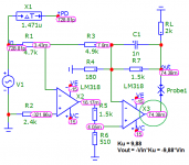
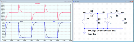
To help you start going seriously. The attached simulates what I think is your point.
First I produce a low-passed squarewave. This is buffered with E1 and inserted in a simple RC low pass filter. This low pass filter is a representation for a well-designed 1st order roll off amplifier.
If you look at the difference between the input and the output of the lowpass filter, you see the same 'error' as you have been showing.
The advantage of showing it this way is that it focusses on exactly the subject issue without muddling it with details about an actual amplifier. If you want to conclude from this that an amp needs some specific parameter(s), then it is easy to implement it in an actual design. Then you have a RESULT from all your work!
Jan
Attachments
"If this is the case, then if you feed the amp with a square wave (passed through a 30kHz low pass as you used earlier), then we should see those errors at each edge of the square wave. Is that correct?"
Yes!
It is really amazing how “first cycle distortion” became every cycle distortion.
I’m even more amazed that you are not ashamed to say “But your intellect is not enough to understand this” to the distinguished member.
Jet, this person still politely discuss with you in effort to help other understand your idea (if there is any).
Yes, politeness is trait of great people. Rudeness is trait of the opposite sort.

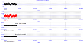
Jan, here is a test of a model of a real amplifier developed by a Russian developer for recording studios as a reference. With this amplifier, you can hear the smallest nuances of sound material, it's like looking at a picture with a microscope.
Before transferring the order to the studio, the author tested it on a large number of music lovers and musicians. All gave the highest rating to the sound quality.
The main parameter on which the sound quality depends is the signal propagation delay (tPD). This amplifier has a tPD = 1.2 ns! (completely according to Cyrill Hammer). True, there is a slight rise in the group delay (up to 30 ns) above 300 kHz. On the one hand, the rise is small (3 times lower than the maximum allowable), and on the other hand, it is far beyond the audio range, so the sound quality is no longer affected.
Here is the result of rendering on a multitone. The calculation is very slow, so I had to interrupt it. But even from this segment of the test, it is clear that the distortion introduced by the amplifier is negligible.
Attachments
Jan, here is a test of a model of a real amplifier developed by a Russian developer for recording studios as a reference. With this amplifier, you can hear the smallest nuances of sound material, it's like looking at a picture with a microscope.
You are so full of ********.
This is as close to meaningless nonsense as it is possible to get.
Do you actually think that we are complete idiots.
Regards
Soundengineer.
Stein
@jan
When Petr doesn't answer or comment your simulation in #537, it speaks for it self.
I admire your patience
/örjan
When Petr doesn't answer or comment your simulation in #537, it speaks for it self.
I admire your patience
/örjan
Jan, here is a test of a model of a real amplifier developed by a Russian developer for recording studios as a reference. With this amplifier, you can hear the smallest nuances of sound material, it's like looking at a picture with a microscope.
Before transferring the order to the studio, the author tested it on a large number of music lovers and musicians. All gave the highest rating to the sound quality.
The main parameter on which the sound quality depends is the signal propagation delay (tPD). This amplifier has a tPD = 1.2 ns! (completely according to Cyrill Hammer). True, there is a slight rise in the group delay (up to 30 ns) above 300 kHz. On the one hand, the rise is small (3 times lower than the maximum allowable), and on the other hand, it is far beyond the audio range, so the sound quality is no longer affected.
Here is the result of rendering on a multitone. The calculation is very slow, so I had to interrupt it. But even from this segment of the test, it is clear that the distortion introduced by the amplifier is negligible.
Petr_, with all due respect to your friends, but we were having a technical discussion. It really doesn't matter for a technical discussion what you and your friends find about this or that amplifier. I couldn't care less to be honest. Even if we were not having a technical discussion, do you really think we would be impressed by what you and your friends find about an amp build by another friend you obviously worship?? Of course that amplifier sounds great - it is impossible not to!
If we can continue the technical discussion. Do you agree that the magnitude and the duration of the 'errors' I showed in my previous post ultimately depend on the amplifier bandwidth/frequency response? That the 'error' will be less when the amp has more bandwidth, and less group delay?
I will add another sim to further illustrate. Here I have added global feedback around the amp with an open loop gain of 60dB. It is still 1st order with a 2nd order roll off added at 100 x the 1st order frequency. The phase shift from the two roll offs is less than 180deg when the gain drops down so there is no sign of instability.
Because of the feedback, there is again the error voltage at the input; at the square wave edges, the amp output cannot follow the input and the difference between them at the input shows the higher error.
Is this a bad thing?
BTW, the Vin plot clearly shows the amp open loop gain.
Jan
Attachments

Last edited:
Jan, nice avatar.
"Before I respond just give me a moment to bask in the radiance of your wisdom"..
"Before I respond just give me a moment to bask in the radiance of your wisdom"..
Vinyl replay has FCD
CD replay has FCD
Digital sources have FCD
Therefore, it is not possible to provide any corroboration of what is claimed for sound quality.
CD replay has FCD
Digital sources have FCD
Therefore, it is not possible to provide any corroboration of what is claimed for sound quality.
Last edited:
Jan:
“ Do you agree that the magnitude and the duration of the 'errors' I showed in my previous post ultimately depend on the amplifier bandwidth/frequency response? That the 'error' will be less when the amp has more bandwidth, and less group delay?”
Jan, what have I been talking about for how long and trying to prove it with various examples of models of real amplifiers?
Above I talked about speed parameters such as:
SR, tPD, full power bandwidth. Rise Time is essentially the same parameter as SR measured slightly differently.
All speed parameters are linked.
Usually, only the frequency response is recorded in a small-signal mode. In this case, the full power bandwidth has nothing to do with the unity gain bandwidth. In the small-signal mode, the bandwidth of the two amplifiers can be the same, say, 2 MHz (-3 dB), and the full power bandwidth of one is 1 MHz, and the second one has only 100 kHz (or even lower, for example, 60 kHz). I gave examples.
In addition to the frequency response, at best, the loop gain is measured, phase and gain margins are given.
Having achieved a loop gain at a frequency of 20 kHz, at least 50 ... 60 dB are removed using Audioprecision THD and rejoice at low distortion. This is followed by a real beep and frustration often ensues. Only rare industrial amplifiers, whose circuits are closed, have good sound.
I am trying to pay special attention to the group delay of the signal transmission and not only to its magnitude, but also to the behavior behind the sound strip.
It's no secret that DC amplifiers are in a more advantageous position for which tPD is constant from fractions of Hertz. When using integrators to maintain the bias (zero) at the output, you have to be very careful not to harm. The illiterate use of integrators is often the cause of additional distortion.
Well, exercises on RC-chains (what you are doing now) in Russian is called “training on cats” - comedy phrase. To do this, you need to stock up on popcorn and exercise.
Well, I was trying to develop the discussion toward some logical direction where we can make conclusions from what we see in measurements.
I know you have been talking about the things you mention for months, and getting nowhere. Does that not frustrate you? Why not start from 'the cat' and take us by the hand and develop your case? Step by step? Maybe you are not used to that, maybe you are not used to develop something methodically to convince people you have discovered something important. There's lots of people who want to help you here, but it doesn't work if you continue to **** them off or just ignore their postings. Why not build on my post #543 and discuss what the effects of this are for an amplifier? Is it bad for an amplifier? If it is, is there some maximum of the 'error' that is still acceptable for low distortion? What is the relative importance of the input signal bandwidth and the amplifier bandwidth to make sure this does not become a problem? You probably have thought about this for a long time already.
"trying to prove it with various examples of models of real amplifiers?"
Are you kidding? You are in a technical discussion, and you want to 'proof' your point by saying you listened to amplifier X and it sounded great therefor that proves my point? Really?
Several statements in your posts have nothing to do with the discussion subject, they are personal or they are just wrong. You really have to do better not in technical stuff, I am sure you are a smart engineer. But you really need to learn to communicate and to focus on what you want to tell us, instead of changing the point of your posting every time.
And BTW, rise time and slew rate are two totally different things. Rise time is a small signal property, slew rate is large signal. They are not 'the same thing only measured differently'. One is a linear phenomenon, the other is decidedly non-linear. The processes that cause them in an amp are different. Check it out and you will be wiser again.
Jan
Last edited:
- Home
- Amplifiers
- Solid State
- Musings on amp design... a thread split