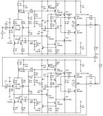
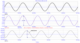
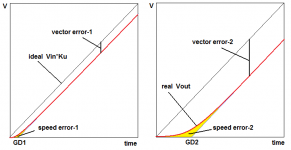
Hafler's test measures vector error.
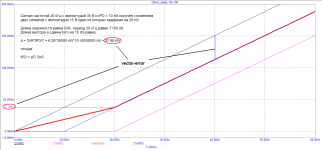
According to the AKSA message, the vector error in the Hafler test should be in the range from minus 50 dB to minus 70 dB (or from 1/3000 ... 1/300 of the output voltages).
With 60 V output signals, the vector error in the worst case should not exceed 200 mV.
And what do we have in the examples discussed above?
Attachments
Compare nonlinear distortion with such different kind of compensation (TMC, what is OIC vs. simple Miler around VAS with output stage outside global NFB) in identicall amplifiers. It is much more important as different group delay, which is inaudible..You are fixed to one unimportant parameter, " because of one tree you do not see whole forrest"🙂
Last edited:
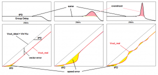
the sound quality is strongly influenced not only by the signal propagation delay (tPD), but also by its behavior both in the passband and beyond the bandwidth. Here are some possible examples ...
" because of one tree you do not see whole forrest" – said the blind man who is led by the blind
" because of one tree you do not see whole forrest" – said the blind man who is led by the blind
Attachments
Last edited:

It is hopeless.. 🙄
.. make real amplifiers for more than 30 years..😉said the blind man who
Last edited:
And now please add what the square wave looks like, corresponding to these three variants of the behavior of the delay time and the signal shape. I think it will be very informative.the sound quality is strongly influenced not only by the signal propagation delay (tPD), but also by its behavior both in the passband and beyond the bandwidth. Here are some possible examples ...
Last edited:
BV - you say that you have been working on the development of audio amplifiers for more than 30 years, and you also claim that I "do not see the forest" behind one tree. It's hard to say what you mean by "one tree", maybe FCD, I don't know.
Well, in that case, give the waveform of the Haffler test of your best amplifier, as well as its parameters such as the slew rate, GDelay, load capacity (maximum output current), as well as the full power band, as the best manufacturers of audio equipment do today, well, of course those parameters by which you mean "forest".
Let's make a reservation right away that such parameters as THD and IMD have no practical meaning, since they do not correlate with the sound quality.
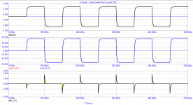
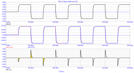
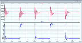
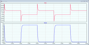
Hafler test using a rectangular signal and a 100 kHz low-pass filter (as in DIM-100). No comments
Which amplifier do you think will more accurately convey the smallest nuances of sound material?
Which amplifier do you think will more accurately convey the smallest nuances of sound material?
Attachments
No difference, because those differences in 100kHz low passed reproduction have nothing to do with 'accurately convey the smallest nuances of sound material'.
The 100kHz low pass is a way to characterize the amp transfer function. And you showed that a 'slower' amp has a larger error with this signal than a 'faster' amp.
But it is not the same as a normal audio signal. Audio has much less bandwidth and not a linear distribution. Therefor, you cannot extrapolate the results of this test to your question.
If you would want to know the audio differences, use a signal that looks more like audio.
Jan
Last edited:
Hafler test using a rectangular signal and a 100 kHz low-pass filter (as in DIM-100). No comments
Which amplifier do you think will more accurately convey the smallest nuances of sound material?
Now we are getting somewhere.
Lock at the error spikes, on each time we have a fast rise time/high frequency content. Not only in the first cycle!
/örjan
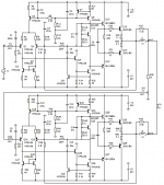
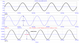
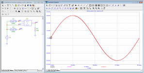
The simulations above give a good impression on the response and stability of the amplifiers. Both are well behaved as shown by the absence of any ringing.
The conceptual form is shown as petr_1 fb below. It is a amp with a 2nd order roll-off, where the 2nd break frequency is 100 times the first. Many audio power amps show a similar transfer characteristic. Both have an ol gain of 60dB, with a cl gain of 11.
The second example, petr_1 fb 2nd, has the two poles at the same frequency. That means that stability is marginal because the roll off leads to high phase shift while the gain is still not zero.
Jan
Attachments
BV:
"You are fixed to one unimportant parameter, " because of one tree you do not see whole forrest" "
I really hope that BV with 30 years of design experience will do the Hafler test on its best design and show me the "whole forest" that I can't see because of the "one tree".
best regards
Petr
In my opinion, it is necessary to legitimize the Hafler test in the form of a standard along with the DIM-30 and DIM-100 tests.
As you can see, the test is extremely simple, does not require special measuring instruments, you can test on any signals, including real sound ones.
As you can see, the test is extremely simple, does not require special measuring instruments, you can test on any signals, including real sound ones.
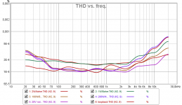
I can show you whole set of real standart audio measurements, as THD vs. freq, THD vs. pwr, spectra for various signal and power for DIM, TIM, CCIF, IMD, multitone and many more , which I make very often,one sample is attached. But you prefer "virtual reality" and believe only in simulations and very unprecise indicative Hafler test...So it has in this case no sens to argument with facts..
Attachments
Last edited:
In my opinion, it is necessary to legitimize the Hafler test in the form of a standard along with the DIM-30 and DIM-100 tests.
As you can see, the test is extremely simple, does not require special measuring instruments, you can test on any signals, including real sound ones.
I don't understand - please show on your amp with pictures and instruction + your test setup and process.
//
for those who want to understand vector distortion
BV,
The fact that no standard test today correlates with sound quality has been repeatedly said by John Curl and other well-known developers who "ate the dog" on measurements, and you still trust them.
Read the article carefully:
A Future Without Feedback?
Martin Colloms, Stereophile, January, 1998, vol. 21 No.1, p.87
do not be lazy and do the Hafler test of two amplifiers of different sound and you will understand what it costs
Attachments
Last edited:
You are kidding..I know such articles and I simply dissagre with many claims, because are not based on reality.. Some measurement artifacts in submicroseconds duration have nothing to do with sound, it is not audiosignal. But spectral changes in audioband yes..
And show us some real measurements, not such trivial simulations.. "sound quality"...judged by which ear?
And show us some real measurements, not such trivial simulations.. "sound quality"...judged by which ear?
Last edited:
I don't understand the hang-up on the Hafler test. It is quite insensitive and hard to keep stable, and can only be 'documented' by subjective perceptions. But it was the best they could do half a century ago without breaking the bank.
These days, a $100 sound card and some free software can show much more distortion detail and is much more consistent in results that can be easily objectively documented.
Jan
These days, a $100 sound card and some free software can show much more distortion detail and is much more consistent in results that can be easily objectively documented.
Jan
The fact that no standard test today correlates with sound quality
GedLee metric
- Home
- Amplifiers
- Solid State
- Musings on amp design... a thread split