So, Petr_, can we discuss, based on your findings, what is the impact of those square wave errors on the amplifier performance? Do you think they cause additional distortion, and if so, how?
Jan
Jan
Jan, the other day I came across the following thread ... Pavel Makura, who seems to be a fan of your school, wrote the following:
John Curl's Blowtorch preamplifier part III
«The problem of these debates is that almost no one comes with real data, real measurements, facts. Instead, general statements and stories are provided, without any quantification, without any possibility of qualified discussion. Then it looks like a spectacle for admiring unqualified crowds.»
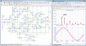
I took a look at your report on the amplifier performed almost 1: 1 from the book by Douglas Self. Nothing new. Here are the results of testing his model. Good for a subwoofer.
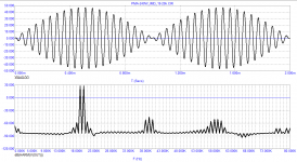
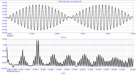
the second IMD test is performed according to Hiraga
John Curl's Blowtorch preamplifier part III
«The problem of these debates is that almost no one comes with real data, real measurements, facts. Instead, general statements and stories are provided, without any quantification, without any possibility of qualified discussion. Then it looks like a spectacle for admiring unqualified crowds.»
I took a look at your report on the amplifier performed almost 1: 1 from the book by Douglas Self. Nothing new. Here are the results of testing his model. Good for a subwoofer.
the second IMD test is performed according to Hiraga
Attachments
And what does Pavel have to do with it at all? We are talking about your statements and their truthfulness, and you are turning the arrows and trying to put the composition on a different path. Is this a deliberate distraction of the focus of attention? Yan is deliberately trying to keep you strictly in line with a specific discussion, but you are jumping from side to side like a hare over bumps.
If you read carefully, you will see that this is not even the development of Pavel Maсura, but a scheme based on the Luxman L-85V with minor changes. What Olympic heights did you expect?
If you read carefully, you will see that this is not even the development of Pavel Maсura, but a scheme based on the Luxman L-85V with minor changes. What Olympic heights did you expect?
Last edited:
Jan, how many times have you tried to humiliate me by stocking up on popcorn to keep you laughing all day. Then you recommend me not to deal with audio amplifiers, like I don't understand anything in this matter. In fact, I see that you just can't understand how working the vector distortion selector that Baksandal proposed and which was used and used by many radio amateurs around the world, including Walt Jung, also used when researching SID. I also use this method virtually and have already explained to you the peculiarities of my approach several times, but again you are asking about the multipliers on the graphs. If you do not understand for the umpteenth time, then this is not for you, just ignore and pass by, do not confuse the fragile minds of young people.
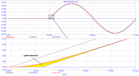
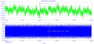
Here is an example of a short burst from just two periods (I don't even remember where I borrowed it from). The pronounced distortions of the first half-cycle are clearly visible (for you FCD). At the end of the burst, prominent oscillatory processes are caused by the behavior of the GD beyond the passband.
Here is an example of a short burst from just two periods (I don't even remember where I borrowed it from). The pronounced distortions of the first half-cycle are clearly visible (for you FCD). At the end of the burst, prominent oscillatory processes are caused by the behavior of the GD beyond the passband.
Attachments
@Fagos: Yes. The quote from Petr_ from the BT thread is taken out of context and actually means the opposite of what he thinks it means.
But also, what has that to do with the discussion we are trying to conduct? I have no idea what amp that is, no idea what 'my report' is, and whether or not it has anything to do with the discussion.
@ Petr_: yes, in the beginning I have mocked you, that was not good and I apologize for that.
To the content: as long as you continue to bring up FCD nobody is going to believe anything you say. FCD is not an audio test signal, and nobody will be impressed with a measurement of an illegal signal.
We have a saying in my country: 'even a donkey will not bump into the same rock twice'. You keep on bumping into the same rock over and over again, maybe believing that some day the rock has magically disappeared. Not going to happen.
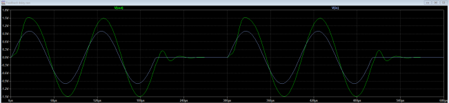
You do it again in the previous post: just out of the blue. The graph does not show distortion, it shows the usual ringing from a signal outside the normal operating bandwidth of the circuit. You can't just throw up stuff like that and expect people to decipher it.
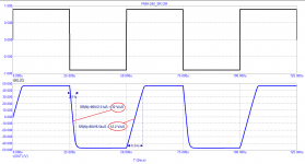
I suggested a way forward: use a test signal that everybody can accept because they use it them selves: a low-passed square wave. It should be acceptable by you too as it causes exactly the same errors that you are trying to present.
You obviously are a smart engineering person, but maybe you are not experienced in approaching an investigation in a logical, step by step way, to get to a solution or at least a clear problem statement. That's OK, we all started from zero, but many here are willing to help, just accept it.
I asked a simple question: the error voltages shown on the amplifier from the square wave signal, are they a problem for the amp? Do they cause distortion? If they are a problem, why?
Then if we know what the problem is (if any) we can talk about how to design the amp so it is no longer a problem.
But I've tried enough, I will be signing off unless it will show something worthwhile to take part in.
Jan
But also, what has that to do with the discussion we are trying to conduct? I have no idea what amp that is, no idea what 'my report' is, and whether or not it has anything to do with the discussion.
@ Petr_: yes, in the beginning I have mocked you, that was not good and I apologize for that.
To the content: as long as you continue to bring up FCD nobody is going to believe anything you say. FCD is not an audio test signal, and nobody will be impressed with a measurement of an illegal signal.
We have a saying in my country: 'even a donkey will not bump into the same rock twice'. You keep on bumping into the same rock over and over again, maybe believing that some day the rock has magically disappeared. Not going to happen.
You do it again in the previous post: just out of the blue. The graph does not show distortion, it shows the usual ringing from a signal outside the normal operating bandwidth of the circuit. You can't just throw up stuff like that and expect people to decipher it.
I suggested a way forward: use a test signal that everybody can accept because they use it them selves: a low-passed square wave. It should be acceptable by you too as it causes exactly the same errors that you are trying to present.
You obviously are a smart engineering person, but maybe you are not experienced in approaching an investigation in a logical, step by step way, to get to a solution or at least a clear problem statement. That's OK, we all started from zero, but many here are willing to help, just accept it.
I asked a simple question: the error voltages shown on the amplifier from the square wave signal, are they a problem for the amp? Do they cause distortion? If they are a problem, why?
Then if we know what the problem is (if any) we can talk about how to design the amp so it is no longer a problem.
But I've tried enough, I will be signing off unless it will show something worthwhile to take part in.
Jan
Last edited:
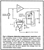
This circuit comes from an ADI App-Note 245 by Wurcer & Jung:
https://www.analog.com/media/en/technical-documentation/application-notes/5866763300941AN245.pdf
I experimented with it quite a bit, that's why I recognized it at first sight.
Regards,
Braca
https://www.analog.com/media/en/technical-documentation/application-notes/5866763300941AN245.pdf
I experimented with it quite a bit, that's why I recognized it at first sight.
Regards,
Braca
petr_2009
Do you actually think Baxandall and Jung were unaware of what you are trying to claim?
Here are their conclusions after significant study.'
Peter Baxandall
'Provided an amplifier is not overloaded, and provided it has sufficient feedback to make to make the distortion when not slew-rate limiting adequately low, there is certainly no absolute necessity for the slew-rate limit of the amplifier to be any larger than the maximum rate of change, or slew rate, of the waveforms handled by it.
Walt Jung
'Once sufficient linearity and slew rate have
been provided in a design, there may actually be little gained
by boosting SR further (to far beyond that necessary).
The optimum audio amplifier is best designed with all contributions given proper perspective'
Jan has repeatedly tried to tell you that the square wave test achieves the same thing as your FCD test. I have demonstrated this. Yet you assiduously avoid addressing this engineering perspective. Instead, there is repeated obfuscation with tangent topics.
One of my amplifiers is in a commercial recording studio. What does this mean? It means nothing because it does not contribute anything, not one iota, to the engineering discussion at hand.
Last edited:
Bob Cordell Interview: Negative Feedback
Bob:
“As I mentioned earlier, there is nothing wrong with first cycle analysis or squarewave analysis as long as it is somewhat reasonably bandlimited to, say, 100 kHz or so. Even Otala understood the need to bandlimit the squarewave he used in his DIM test to 100 khz or less. To not do so can lead to mis-leading results.”
As you can see, Jan, Bob Cordell rehabilitated FCD while Graham was still alive, and you still forbid me to use that term and make fun of me. I told you that he laughs who laughs last. You just have to wait ...
Bob Cordell Interview: Negative Feedback
AKSA
“Distortion specs are normally given steady state, sinusoidal, constant frequency. The technology is not presently able to give such measures with real world signals. Carver is in fact nulling dynamic distortion with real music, one of the great unknowns. He is using a subtraction process between two amplifiers to isolate the error 'sound', and tweaking until it is 50-70dB below the line signal.”
Presumably, Carver uses the Hafler test, which I have already quoted along with the Baxandall test.
What is the attenuation of the vector error signal by 50 ... 70 dB. This means that the level of the vector error is 300 ... 3000 times less than the signals at the outputs of the amplifiers. Let's imagine that we use a triangular signal with a frequency of 10 kHz (100 μs period) as a test signal, while its amplitude at the outputs of the amplifiers is 60 V from peak to peak. If the signals at the outputs of the amplifiers are equal, the difference signal will be a rectangular signal with an amplitude of 0.2 to 0.02 V.
Time Propagation Delay is calculated by the formula:
tPD = aT / 4A
where
a - is the amplitude of the rectangular signal at the load;
T - is the period of the triangular signal;
A - amplitude of the triangular signal at the outputs of the amplifiers
In this case
tPD (max) = 0.2 * 100/4 * 60 = 20/240 = 0.083 μs = 83 ns
tPD (min) = 0.02 * 100/4 * 60 = 2/240 = 0.0083 μs = 8.3 ns
I have repeatedly mentioned that the signal propagation delay time should not exceed 100 ns. As you can see, Carver is doing just that.
Impressions of popcorn consumer
Well petr, it is rare to see such victorious quoting of Bob Cordell where in fact you shot off your own foot.
He says that for such analysis signal must be bandwidth limited, otherwise results will be misleading.
This is exactly what you’ve been told more than hundred times by various thread participants, yet you refuse to accept this and all your simulations are based on unlimited bandwidth test signal.
Bob Cordel says that results will be misleading. Everybody and their dog say the same and you don’t accept.
If you carefully read what Bob wrote, you will see that you need to limit the signal band, which means that you need to put a filter with a cutoff frequency of 100 kHz in front of your original sine source. Such a filter will smooth out your break and the results will be much better, since the amplifier will not be forced to chew too wide-band signal. So you laugh early.Bob Cordell Interview: Negative Feedback
Bob:
“As I mentioned earlier, there is nothing wrong with first cycle analysis or squarewave analysis as long as it is somewhat reasonably bandlimited to, say, 100 kHz or so. Even Otala understood the need to bandlimit the squarewave he used in his DIM test to 100 khz or less. To not do so can lead to mis-leading results.”
As you can see, Jan, Bob Cordell rehabilitated FCD while Graham was still alive, and you still forbid me to use that term and make fun of me. I told you that he laughs who laughs last. You just have to wait ... .
Will you make a comparison of the signals before and after the filter? Maybe we'll laugh together, who knows...
Can you explain where this formula came from and how it was obtained?Presumably, Carver uses the Hafler test, which I have already quoted along with the Baxandall test.
What is the attenuation of the vector error signal by 50 ... 70 dB. This means that the level of the vector error is 300 ... 3000 times less than the signals at the outputs of the amplifiers. Let's imagine that we use a triangular signal with a frequency of 10 kHz (100 μs period) as a test signal, while its amplitude at the outputs of the amplifiers is 60 V from peak to peak. If the signals at the outputs of the amplifiers are equal, the difference signal will be a rectangular signal with an amplitude of 0.2 to 0.02 V.
Time Propagation Delay is calculated by the formula:
tPD = aT / 4A
where
a - is the amplitude of the rectangular signal at the load;
T - is the period of the triangular signal;
A - amplitude of the triangular signal at the outputs of the amplifiers
In this case
tPD (max) = 0.2 * 100/4 * 60 = 20/240 = 0.083 μs = 83 ns
tPD (min) = 0.02 * 100/4 * 60 = 2/240 = 0.0083 μs = 8.3 ns
I have repeatedly mentioned that the signal propagation delay time should not exceed 100 ns. As you can see, Carver is doing just that.
In addition, as far as I understand, Carver uses a real signal, which means that his band is limited from the source. A triangular signal will probably give us inflated values of distortion and the comparison will not be correct.
I will also add that according to my estimates, you have a group delay on a sinusoidal signal with a frequency of 20 kHz and 0.03% should be about 200ns, which is equivalent to the cutoff frequency of the first-order filter about 770kHz. This will give the desired value of the input-output vector error.
Last edited:

Pure delay creates no harmonics.. So it is not distortion, but only delay..Substraction of direct and dealyed signal have no information about distortion, only about delay/phase shift. Right test arangement should look like this

Last edited:
Right. If the phase shift/delay compensation network would distort, the whole test would be useless.
Jan
Jan
AKSA talked about testing using the Hafler method, in which there is no need for phase correction. Baxandall phase correction is difficult to perform with sufficient accuracy, moreover, it is undesirable since it excludes phase distortions introduced by the amplifier.
Attachments
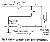
AKSA talked about testing using the Hafler method, in which there is no need for phase correction. Baxandall phase correction is difficult to perform with sufficient accuracy, moreover, it is undesirable since it excludes phase distortions introduced by the amplifier.
In my opinion it's wrong to talk about phase distortion in this context.
The correction network corrects for the low pass caused by the amp. This is linear and distortion is caused by non linearity.
/örjan
I agree. Phase distortion is a measure of varying phase shifts in a signal chain. It is a linear phenomenon that does not create new signal frequencies.
On the other hand, harmonic distortions are caused by non-linearities in a signal chain and do create new signal frequencies, harmonics of the fundamental tone(s) and intermodulation products.
Although phase distortion and harmonic distortion use similar words, it is important to understand that the causes and effects are completely different and should not be confused.
The Baxandall test is designed to measure non-linear harmonic distortion by suppressing the fundamental in the amplifier output. The amplifier will have phase shift so to cancel its output by subtracting the fundamental, you need to introduce the same phase shift in the subtraction chain. It generally involves tweaking R-C attenuators.
This phase distortion/phase shift and its correction do in no way limit the ability of the method to measure harmonic distortion.
Jan
Attachments

Last edited:
If phase shift is not constant but depends on some variable like signal amplitude, it will create new non-harmonic signal frequencies.
... You just have to wait ... ...
For what? Are you releasing an amp from your drawingbaord?
//
If phase shift is not constant but depends on some variable like signal amplitude, it will create new non-harmonic signal frequencies.
Agree, but that's why I said, in this context, as in why you should use the passive correction network in the Baxandall circuit
Edit, @peufeu, you probably know but to clarify my previous post.
/örjan
Last edited:
- Home
- Amplifiers
- Solid State
- Musings on amp design... a thread split