Yes: The Gedlee Metric Demystified and it nicely illustrates that the use of THD for amplifier testing is not because designers think it is correlated with sound quality, but rather because well-suited tests like the GedLee metric are above a lot of people's level.
As the saying goes: for every difficult, complex problem there is an easy to understand, simple and wrong answer.
Jan
As the saying goes: for every difficult, complex problem there is an easy to understand, simple and wrong answer.
Jan
Last edited:
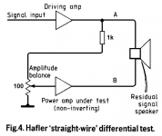
petr_2009, If Hafler should tell us something about audible artefacts ( about changes in sound), so output (pin "out" in your picture) have to be bandlimited to e.g 80kHz, as standard distortion tests, or to 20Hz-22kHz. Because no one can hear and no speaker can reproduce 100-500ns peaks...And Hafler slowly changed to Baxandall test..
Influence on sound have only products on amplifier otput, which are in audioband . Any potentially audible sound change must lie in audioband. And must carry "audible" energy. So simple is it...
Influence on sound have only products on amplifier otput, which are in audioband . Any potentially audible sound change must lie in audioband. And must carry "audible" energy. So simple is it...
The Hafler and Baxandall tests are too primitive to give any consistent and worthwhile results with modern very low distortion audio equipment.
The best methods like multitone testing gives all kinds of distortion and noise in the presence of signal, coming very close to actual music conditions.
If you read for instance Belcher from 1978 (!) you already see the contours of such test methodologies, but the lack of high performance low cost digital number crunching at the time led it slide into forgetfulness. But they very well knew the issues and the conceptual solutions, and I am sure people at AP like Rich Cabot knew these papers by heart!
Jan
Attachments
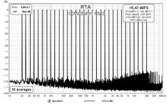
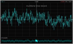
Yes and it looks a lot like music except maybe for the crest factor. But I think that can be adjusted in REW.
Jan
Jan
Measurements can hardly tell anything past a minimal amount of effective distorsion.
Reason is that harmonics and intermodulation products wich are chased by the measuring gear are already presents in huge proportion in any musical content, instruments have sounds that have massively amount of harmonics and intermodulations products are inherent once two sounds are mixed acoustically, be it on a live recording or when getting out of speakers whose distorsion is magnitudes higher than the one produced by an average amp.
Reason is that harmonics and intermodulation products wich are chased by the measuring gear are already presents in huge proportion in any musical content, instruments have sounds that have massively amount of harmonics and intermodulations products are inherent once two sounds are mixed acoustically, be it on a live recording or when getting out of speakers whose distorsion is magnitudes higher than the one produced by an average amp.
Agree on the speakers causing IM, although, if you read up on the GedLee thread, surprisingly little, sometimes even less than the amp!
I don't think acoustic IM is a factor; to cause IM, you need a non-linear medium and air only gets nonlinear at extreme high levels, probably chasing you away and cause bleeding ears long before that!
Jan
I don't think acoustic IM is a factor; to cause IM, you need a non-linear medium and air only gets nonlinear at extreme high levels, probably chasing you away and cause bleeding ears long before that!
Jan
BV, with your experience to assemble a Hafler circuit in 3 minutes, test on the same multi-tone signal and on a 10 kHz sine wave and show the oscillograms. As you can see, the signals are in the audio range, and not what Jan Didden writes about. Vector distortions are perfectly described in the book by Jiri Dostala, calculations and graphic illustrations are provided.
Vector distortion is directly related to signal propagation delay and is proportional to GDelay. It is known from psychoacoustics that the human ear reacts most of all to GDelay.
Vector distortion is directly related to signal propagation delay and is proportional to GDelay. It is known from psychoacoustics that the human ear reacts most of all to GDelay.
Attachments
Why should I do it?? I tried it about 25 years ago..It will be lost time and no new information gained, this test is very inacurate.
Read again
Musings on amp design... a thread split.
Musings on amp design... a thread split.
you will find answers why it s so..
Read again
Musings on amp design... a thread split.
Musings on amp design... a thread split.
you will find answers why it s so..
And try think about facts, that time delay alone and band limiting are not nonlinear distortions, they create no new artefacts. And that real music signals are always bandlimited to audioband , maybee harmonics of instruments sound are slightly higher. But 100kHz bandlimit is more than enough.If Hafler should tell us something about audible artefacts ( about changes in sound), so output (pin "out" in your picture) have to be bandlimited to e.g 80kHz, as standard distortion tests, or to 20Hz-22kHz. Because no one can hear and no speaker can reproduce 100-500ns peaks...
But no in 100-500ns range 🙂that the human ear reacts most of all to GDelay.
Last edited:
It is known from psychoacoustics that the human ear reacts most of all to GDelay.
Where is that documented?
Jan
Explanations for the post
Musings on amp design... a thread split.
The illustrations show the relationship between the vector error (distortion) and the delay time. In some high-speed op-amps, the signal propagation delay is quoted as tPD (time Propagation Delay).
The first figure shows four sinusoids, but since they are delayed relative to each other for a short time, they visually merge. The signal of the generator with a frequency of 20 kHz has an amplitude of 15 V. When two signals are added, one of which is delayed for a short time, the amplitude of the output signal practically doubles and is equal to 30 V. In order for all four signals to be of the same amplitude for signals IN1, IN2 and tPD, a factor of 2 is applied ...
The initial section of the signal, marked with a rectangle, is shown in the following figure.
It can be seen from the second figure that when the original signal (black) and the signal delayed by 20 ns (pink) are added, the output signal (red) is formed with a half-time delay, i.e., 10 ns. Moreover, in the initial section, distortions inevitably occur over 20 ns, i.e., over 2 * tPD. Jiri Dostal mentions velocity distortions in his book, but does not give a clear definition of what it is. I took it upon myself to call this type of distortion velocity, since it is directly related to such a velocity parameter as tPD. In amplitude, these distortions are equal to vector distortions, and in time 2 * tPD.
The figure also shows a calculation showing a direct dependence of vector distortion on tPD.
On a note!
In the steady-state mode, there are no speed distortions, only vector distortions that are not measured by any tests other than simple signal subtraction, as is done in the Hafler test. Velocity distortion occurs whenever both frequency and amplitude of the signal change, which occurs continuously in real audio signals. And since the vector error is proportional to tPD, then the speed distortions are proportional to the vector distortions, and from them one can indirectly judge the quality of the amplifiers. The smaller the vector error, the less the speed distortions introduced by the amplifier, which are elusive by any other tests.
Jan, study psychoacoustics!
You avoid a serious question. Again.
You said:
"It is known from psychoacoustics that the human ear reacts most of all to GDelay".
I asked you where this is documented. You don't know, right? It's just some personal opinion based on nothing.
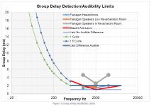
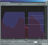
Well, my opinion is that your demand for nS group delay is totally ********. And I can document it, see attached. I am assuming you understand this graph, if not let me know and I'll explain.
Also, if you are interested in reading about audibility of GD also let me know and I can provide references.
Jan
You said:
"It is known from psychoacoustics that the human ear reacts most of all to GDelay".
I asked you where this is documented. You don't know, right? It's just some personal opinion based on nothing.
Well, my opinion is that your demand for nS group delay is totally ********. And I can document it, see attached. I am assuming you understand this graph, if not let me know and I'll explain.
Also, if you are interested in reading about audibility of GD also let me know and I can provide references.
Jan
Attachments
Last edited:
the human ear reacts most of all to GDelay.
No, not if it's flat.
/örjan
as practice shows, even a multi-tone test does not give a true picture of the quality of the amplifier.
At the 126th AES Congress, Professor Farina presented tests on noise signals in which the spectrum changes chaotically, like in audio signals. In the example shown, an octave of noise in the 1 kHz region has been clipped. The test shows that the dynamic range of the amplifier was only 18 to 26 dB. The distortion level reaches 10% or more.
At the 131st AES Congress, J. Atkinson noted that up to this day in sound engineering there are problems to which modern specialists have no answers.
Judging by the reasoning of some gurus, amplifiers with THD = 0.3% on acoustics with THD = 3% should sound the same. But even amplifiers with THD = 0.03% or less sound differently for some reason.
Attachments
Last edited:
Facts about this Farina AES session
Not about chaotically changes in spectrum, but "Changing continuously the suppressed band over time"..Another way to measure nonlinear distortions, way to see distortion artefacts falling in this free band. Nothing about "unexpected" clipping and so. Another sidestep by peter_2009..The method is based on the analysis of the distortion products, such as harmonic distortion products or intermodulation effects, occurring when the system is fed with a wide-band (noise..)signal. Removing from the test signal a small portion of the whole spectrum, it becomes possible to collect and analyze the not-linear response and the noise of the system in that “suppressed” band. Changing continuously the suppressed band over time, we get the Silence Sweep test signal, which allows for quick measurement of noise and distortion over the whole spectrum.
Last edited:
[the dynamic range of the amplifier was only 18 to 26 dB. The distortion level reaches 10% or more.[/QUOTE]
Clever test signal. I like.
Btw it wasn't an amplifier being tested. It was headphones.
Clever test signal. I like.
Btw it wasn't an amplifier being tested. It was headphones.
Yes. It is of technical interest, a typical University paper. But for practical measurements, the multitone in REW (or in an AP for the privileged ;-) is much easier to use.
As I said before, a $ 100 soundcard and the free REW runs rings around any of these old, complex, insensitive and inaccurate tests like the Hafler or Baxandall. Technology has moved on, and I have stuff on my hobby test bench that was unheard of 50 years ago even for professionals.
The late Siegfried Linkwitz once told me that in 1974, when working for HP in California, he was approached by a UK speaker manufacturer (KEF) for a spectrum analyzer so they could do spectrum analysis on speakers. That was iirc a $ 24,000 piece of equipment in 1974. The mind shudders what the equivalent is in 2021 dollars.
https://linearaudio.nl/sites/linear.../siegfried_linkwitz_audioxpress_interview.pdf
Jan
Last edited:
Jan, why did you put out the speaker delay graph?
Where have you seen amplifiers with a signal propagation delay time (tPD) at a frequency of 1 kHz from 1 ms to 2.5 ms (from one period to 2.5 periods), such amplifiers would simply be inoperative.
Jan, the Hafler test is done using a conventional oscilloscope on any signal, and in no case on computer audio cards.
BV, so what about the Hafler test?
- Home
- Amplifiers
- Solid State
- Musings on amp design... a thread split