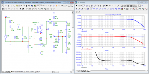
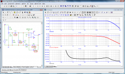
If you close the input of the amplifier to a common one and apply a signal with an amplitude equal to the load resistance (in this case, 8 Ohms) to the output through the load, then the peak current through the load will be 1 A, and the voltage drop at the amplifier output will be equal to the output resistance. You can measure its dependence on frequency, as well as measure the level of its distortion. And although the distortion of the output impedance is more than 4%, the distortion it introduces into the load is negligible, since its resistance is 100,000 times less than the load resistance (8 / 0.00008 = 100000)
see method 2:
Musings on amp design... a thread split.
see method 2:
Musings on amp design... a thread split.
Attachments

the voltage drop at the amplifier output will be equal to the output resistance.
Yes.
You can measure its dependence on frequency, as well as measure the level of its distortion. And although the distortion of the output impedance is more than 4%, the distortion it introduces into the load is negligible, since its resistance is 100,000 times less than the load resistance (8 / 0.00008 = 100000)
Correct, if your amp has a well biased output stage that doesn't do anything funny, and high open loop gain at high frequency, then output impedance is tiny, so distortion caused by its variation is tiny. That was not the case for this amp...
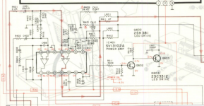
Peufeu, do you have a schematic of the amplifier under test? Can you show her?
Technics SU-600 Stereo Integrated Amplifier Manual | HiFi Engine

Op-amp type M5220 with bipolar transistors at the input. To minimize the offset at the output, it is desirable to have similar impedances at the inputs.
And although there is a blocking capacitor at the input of the final power amplifier at the input, and the presence of a constant voltage at the output of the preamplifier is not dangerous, it is still desirable to minimize the offset. Therefore, here is an option with the elimination of this disadvantage.
And although there is a blocking capacitor at the input of the final power amplifier at the input, and the presence of a constant voltage at the output of the preamplifier is not dangerous, it is still desirable to minimize the offset. Therefore, here is an option with the elimination of this disadvantage.
Attachments
Honestly I won't bother tweaking it, I'm keeping it as a sample of bad sounding amplifier to compare against good sounding amps in measurements. Also it has an integrated hybrid amp which is not modifiable, internal schematics very hard to find.
I personally admire such developments
<<НИРВАНА ХХI>> Гибридный усилитель класса А без общей ООС - YouTube
Dmitry Korzhevsky
"NIRVANA XXI" Class A hybrid amplifier without general NFB
How a tube-transistor amplifier works without general feedback, of its own design. First episode.
Short description
VAS on three lamps: 6N23P - 2 pieces, 6N1P - 1 piece
OPS transistor, class A, 15 W, 800 kHz bandwidth!
Forced cooling with 2 controlled fans
Gain control is remote (radio control), the regulator is on the wafer switch, the transmission is belt-gear.
The author of the Nirvana-21 amplifier Dmitry Korzhevsky made it clear that the output stage is made on a source follower with a current source controlled by a signal from the load. In fact, this is a pseudo-two-stroke stage (OPS) like follower by White and Taylor.
Attachments
John Curl writes in a 1999 interview: “My newest preamp is extremely exotic. I don’t use any negative feedback at all. This is really an experiment. It has local feedback, but it has only a resistor that sets the gain. "
I also decided to make a similar amplifier. That's what came out of it. The main parameters are shown in the diagram.
I also decided to make a similar amplifier. That's what came out of it. The main parameters are shown in the diagram.
Attachments
Renowned audio designer John Curl points out in his interviews that he prefers to make fully balanced circuits. He also notes that the level of the lowest 2nd and 3rd harmonics does not matter in the distortion spectrum. It is necessary to strive for a minimum of odd harmonics starting from the 5th and higher. This is especially true for the 7th and 9th harmonics. As an argument, he cites a magnetic recording in which at the signal peaks the level of the 3rd harmonic could reach several percent. Nevertheless, this did not interfere with enjoying the music. John Curl points out the importance of matching both input and output impedances of a preamplifier. For this purpose, the following model uses buffer stages.
Attachments

Credit should be given to Hawksford, who made a great contribution to the circuitry of amplifiers without negative feedback and their linearization. I want to note that the spectrum was taken in the first period, which cannot be done with standard measuring instruments. In the steady state, the levels of higher harmonics will be lower.
The Hawksford voltage amplifier also needs an output buffer as it has a relatively high output impedance. At the input, I would also include a buffer stage.
The Hawksford voltage amplifier also needs an output buffer as it has a relatively high output impedance. At the input, I would also include a buffer stage.
Attachments
In addition to the high slew rate of the output voltage, John Curl pays great attention to both the first pole (open loop bandwidth) and the high load capacity of the output stage in his designs. The first pole above 20 kHz guarantees a constant loop gain and, accordingly, the output impedance in the audio band. Here's what he says in a 1999 interview:
«Lets say a loudspeaker momentarily changed from 8 ohms to 1 ohm. I have a speaker that does that: a pair of Wilson Audio Tiny Tots. They sound pretty good sometimes, but they are troublesome.
They drop to less than half an Ohm at 2,000 cycles. In some amplifiers it can actually reflect that change of impedance back into the driver stage and change the dynamic gain of the amplifier. The FET driver tends to buffer the load change better than a transistor. And that’s why I prefer FETs in that respect.»
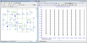
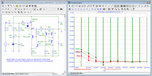
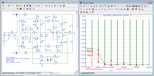
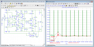
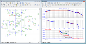
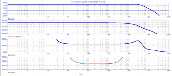
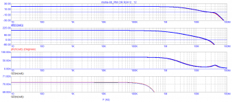
The low frequency of the first pole with a constantly changing load impedance leads not only to amplitude modulation of the signals, but also to phase intermodulation. Let's check the behavior of the group delay at three loads: 2, 8 and 12 ohms of some amplifiers from those considered in this and the adjacent branch earlier. Here are the test results
«Lets say a loudspeaker momentarily changed from 8 ohms to 1 ohm. I have a speaker that does that: a pair of Wilson Audio Tiny Tots. They sound pretty good sometimes, but they are troublesome.
They drop to less than half an Ohm at 2,000 cycles. In some amplifiers it can actually reflect that change of impedance back into the driver stage and change the dynamic gain of the amplifier. The FET driver tends to buffer the load change better than a transistor. And that’s why I prefer FETs in that respect.»
The low frequency of the first pole with a constantly changing load impedance leads not only to amplitude modulation of the signals, but also to phase intermodulation. Let's check the behavior of the group delay at three loads: 2, 8 and 12 ohms of some amplifiers from those considered in this and the adjacent branch earlier. Here are the test results
Attachments
-
 07_R2016-06_PIM.png83 KB · Views: 112
 -
 06_Self_PIM.png83.8 KB · Views: 116
 -
 05_Ampzilla_simple_PIM.png28.9 KB · Views: 81
 -
 04_R2018-06_PIM.png30.3 KB · Views: 84
 -
 03_VAS_Vasiliev&OPS-deemon_PIM.png22.4 KB · Views: 85
 -
 02_misha-88_PIM.png22.2 KB · Views: 81
 -
 01_AMP_SSassen_PIM.png27.5 KB · Views: 113
The rejection of NFB has almost halved the signal transit delay time (tPD) and almost halved the dependence of the tPD change on the load.
see: P H A S E I N T E R M O D ULA T I O N D I S T O R T I O N
I N S T R U M E N T A T I O N A N D M E A S U R E M E N T R E S U L T S
R o b e r t C o r d e l l
see: P H A S E I N T E R M O D ULA T I O N D I S T O R T I O N
I N S T R U M E N T A T I O N A N D M E A S U R E M E N T R E S U L T S
R o b e r t C o r d e l l
Attachments
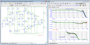
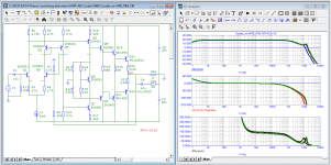
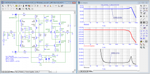
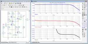
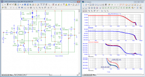
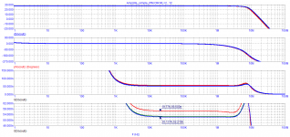
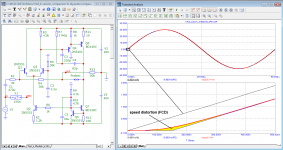
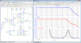
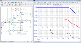
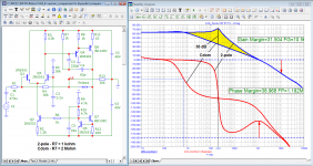
The first figure shows two options for loop amplification: with Cdom and with 2-pole correction. You can clearly see the increase in loop gain at a frequency of 20 kHz by more than 36 dB, which gives a reduction in distortion in the steady state by almost 100 times! However, in dynamics (in the first period), distortions with 2-pole correction are higher.
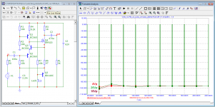
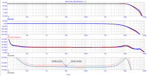
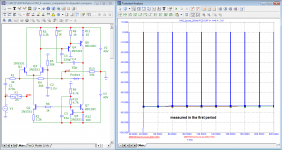
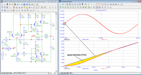
The signal transit time with 2-pole correction in the audio range is also negligible - only a few nanoseconds. However, already from a frequency of 50 kHz, the delay begins to rise, reaching 270 ns at a frequency of 1 MHz. What this leads to is clearly seen from the tests for harmonic distortion in the first periods.
I have already written many times that no measuring device is able to check velocity distortions with the exception of the Baksandall vector method (when measuring in hardware) and the methods demonstrated here using a simulator.
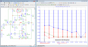
The Miller correction is stupidly borrowed from unity-gain-corrected op amps, as a result the open-loop negative feedback amplifier is an integrator. As you know (or maybe not everyone knows this), the signal at the integrator's output over time acquires a constant component (positive or negative) - it depends on what polarity is the first half-period of the signal.
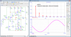
Conclusion: the developer who applied the 2-pole correction for the first time is happy when he tests the amplifier with devices, and the second time he is upset when he is listening to real music.
The signal transit time with 2-pole correction in the audio range is also negligible - only a few nanoseconds. However, already from a frequency of 50 kHz, the delay begins to rise, reaching 270 ns at a frequency of 1 MHz. What this leads to is clearly seen from the tests for harmonic distortion in the first periods.
I have already written many times that no measuring device is able to check velocity distortions with the exception of the Baksandall vector method (when measuring in hardware) and the methods demonstrated here using a simulator.
The Miller correction is stupidly borrowed from unity-gain-corrected op amps, as a result the open-loop negative feedback amplifier is an integrator. As you know (or maybe not everyone knows this), the signal at the integrator's output over time acquires a constant component (positive or negative) - it depends on what polarity is the first half-period of the signal.
Conclusion: the developer who applied the 2-pole correction for the first time is happy when he tests the amplifier with devices, and the second time he is upset when he is listening to real music.
Attachments
-
 08_VAS_Cdom_20kHz-speed_distortion.png73.8 KB · Views: 91
 -
 07_VAS_2pole_20kHz-FCD.png79.9 KB · Views: 89
 -
 06_VAS_Cdom_20kHz-FCD.png82.8 KB · Views: 94
 -
 05_VAS_2pole_20kHz-spectr.png82.7 KB · Views: 92
 -
 04_VAS_Cdom_20kHz-spectr.png83.7 KB · Views: 92
 -
 03_VAS_2pole_Bode.png74.7 KB · Views: 91
 -
 02_VAS_Cdom_Bode.png76.5 KB · Views: 103
 -
 01_VAS_2pole_(Cdom)_Open-Loop-Gain.png100.4 KB · Views: 110
 -
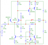 00_VAS_basic_SCH.png18.3 KB · Views: 120
 -
 09_VAS_2pole_20kHz-speed_distortion.png73.9 KB · Views: 99
- Home
- Amplifiers
- Solid State
- Musings on amp design... a thread split