additional drawings
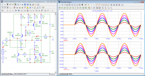
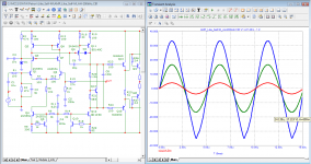
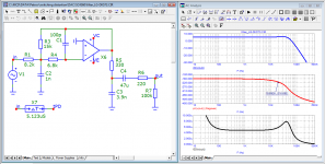
in the small-signal mode, both options are broadband enough, the bandwidth is not less than 1 MHz.
in the small-signal mode, both options are broadband enough, the bandwidth is not less than 1 MHz.
Attachments
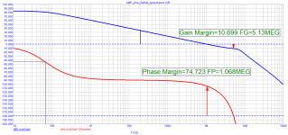
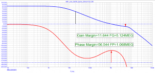
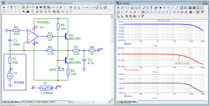
Developers who not only understood circuitry, but also knew how to listen to music, tried to avoid harmful correction by Miller and even more so 2-pole correction and used mainly passive correction. The first pole is high enough - about 70 kHz, which guarantees constant negative feedback depth throughout the entire audio range.
Attachments
-
 006_VAS_JLH-72_200kHz.png82.2 KB · Views: 87
 -
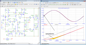
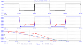
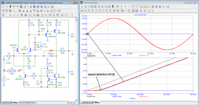 005_VAS_JLH-72_20kHz-speed-distortion.png73.5 KB · Views: 84
 -
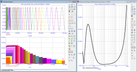
 004_VAS_JLH-72_20kHz-FCD.png65.1 KB · Views: 86
 -
 003_VAS_JLH-72_20kHz-spectr.png73.8 KB · Views: 81
 -
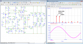
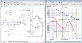
 002_VAS_JLH-72_Open-Loop-Gain.png31.7 KB · Views: 93
 -
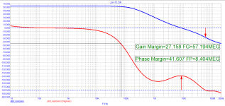
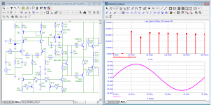
 001_VAS_JLH-72_Bode.png75.5 KB · Views: 99
There's a thing I don't understand about "speed distortion" concept:

Isn't it just a linear effect due to the transfer function?
Isn't it just a linear effect due to the transfer function?
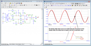
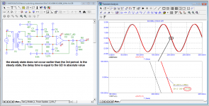
Linear distortion is understood as the distortion of the amplitude and phase in the steady state (i.e., at the end of all transient processes) when there are no additional components (harmonics) in addition to the main signal. There is no steady state in music signals, it is a continuously changing signal. And for accurate signal transmission (so that distortions are minimally noticeable by ear), the signal transmission delay time (GDT) is important, which should be no more than 100 ns (if you count according to Jiri Dostal's formulas), or even a few nanoseconds if you are guided by the statement of Cyril Hammer (Cyril Hammer, The Absolute Sound_ May / June 2012 https://www.moremusic.nl/reviews/passlabs/XP-30-TAS.pdf ) However, it is not only the latency in the audio band that is important, but beyond it. This is shown in the example of 2-pole correction.
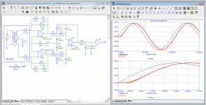
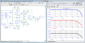
the main parameters of the amplifier model developed according to the recommendations of John Curl are presented in the thread: https://www.diyaudio.com/forums/newreply.php?do=newreply&p=6693027
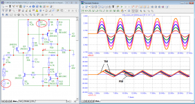
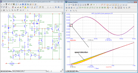
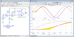
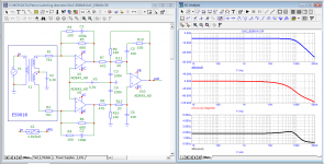
I made a model with similar parameters using the unipolar Cdom correction (Miller's correction is a favorite correction of the popular author of several books, Douglas Self). To do this, I used a typical circuit, made the input differential stage cascode, and added paired transistors in the output stage. For the most equivalent comparison, the power supply of the models is chosen the same by + -40 V. The output stage is made on similar paired transistors and with the same quiescent current of 110 + -10 mA.
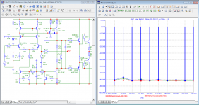
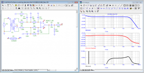
Formally, both versions of the amplifier models (according to the ideas of Curl and according to the book of Self) have approximately the same parameters. In the steady state, the parameters of the Miller-corrected model are even higher. But let's see what is the difference. The level of harmonics of a signal with a frequency of 20 kHz in the first period is at least 10 dB higher. The growth of the output resistance begins at a frequency of 1 kHz, and the phase of the output resistance begins to spin from a frequency of 100 Hz. The signal transit time is twice as long and equal to 150 ns. The slew rate of the output voltage along the edges of the rectangular signal is different: 30 and 50 V / μs. Full power bandwidth is at least 5 times lower (less than 200 kHz). The test results are shown in the figures.
regads
Petr
I made a model with similar parameters using the unipolar Cdom correction (Miller's correction is a favorite correction of the popular author of several books, Douglas Self). To do this, I used a typical circuit, made the input differential stage cascode, and added paired transistors in the output stage. For the most equivalent comparison, the power supply of the models is chosen the same by + -40 V. The output stage is made on similar paired transistors and with the same quiescent current of 110 + -10 mA.
Formally, both versions of the amplifier models (according to the ideas of Curl and according to the book of Self) have approximately the same parameters. In the steady state, the parameters of the Miller-corrected model are even higher. But let's see what is the difference. The level of harmonics of a signal with a frequency of 20 kHz in the first period is at least 10 dB higher. The growth of the output resistance begins at a frequency of 1 kHz, and the phase of the output resistance begins to spin from a frequency of 100 Hz. The signal transit time is twice as long and equal to 150 ns. The slew rate of the output voltage along the edges of the rectangular signal is different: 30 and 50 V / μs. Full power bandwidth is at least 5 times lower (less than 200 kHz). The test results are shown in the figures.
regads
Petr
Attachments
-
 08_AMP_Like_Self-M_Rout-20kHz.png104.6 KB · Views: 97
 -
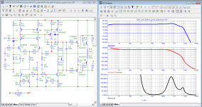
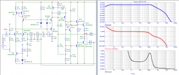
 07_AMP_Like_Self-M_Rout_Bode.png70.2 KB · Views: 105
 -
 06_AMP_Like_Self-M_AH-200kHz.png76.8 KB · Views: 102
 -
 05_AMP_Like_Self-M_speed-dist.png80.9 KB · Views: 90
 -
 04a_AMP_Like_Self-M_THD_vs_Freq_2period.png84.7 KB · Views: 340
 -
 04_AMP_Like_Self-M_THD_vs_Freq_10period.png71.1 KB · Views: 344
 -
 03_AMP_Like_Self-M_20kHz-FCD.png70.9 KB · Views: 370
 -
 02_AMP_Like_Self-M_Loop-Gain.png34.5 KB · Views: 364
 -
 01_AMP_Like_Self-M_Bode.png81.7 KB · Views: 357
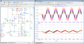
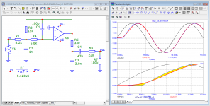
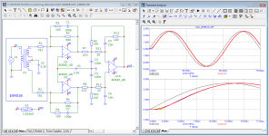
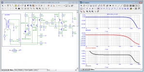
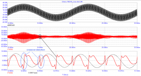
The books by Douglas Self describe the work of 2-pole correction, which allows you to increase the loop gain in the upper part of the audio range. Let's see what this gives on the example of the previously considered model. Loop gain at 20 kHz increased from 35 dB to 60 dB. The level of distortion in the steady-state mode is significantly reduced. The test results using Audioprecision are likely to please the developer. What will happen to the sound? The sound quality depends on the distortions of the first period, which cannot be measured by any measuring device, on the high-speed distortions that appear every time both the frequency of the signal and its amplitude change. Despite the decrease in distortion in the steady state, the distortion of the first period increased by about 10 dB (3 times). Judging by the test, the level of speed distortion has increased significantly. It is the high-speed distortions that are responsible for the accuracy of the transmission of the smallest nuances of sound material.
regards
Petr
regards
Petr
Attachments
-
 06_AMP_Like_Self-M_2pole_speed-dist.png80.6 KB · Views: 124
 -
 05_AMP_Like_Self-M_2pole_20kHz-FCD.png71.6 KB · Views: 101
 -
 04_AMP_Like_Self-M_2pole_20kHz-FCD-spectr.png56.1 KB · Views: 107
 -
 03_AMP_Like_Self-M_2pole_20kHz-THD-spectr.png85 KB · Views: 96
 -
 02_AMP_Like_Self-M_2pole_Loop-Gain.png33.9 KB · Views: 108
 -
 01_AMP_Like_Self-M_2pole_Bode.png85.2 KB · Views: 111
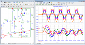
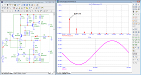
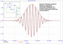
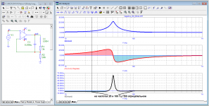
On the question of first cicle distortion (FCD).
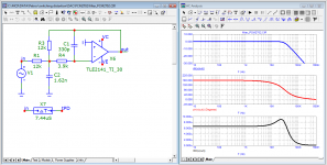
Distortions of the first period of the signal with a frequency of 20 kHz are perfectly visible at the output of the DAC post-filter.
Speed distortions usually appear at the very beginning of the period. The shorter the signal transmission delay time, the less these distortions. With the GDT constant in the entire audio range, immediately after the high-speed distortions, the signal almost immediately goes to the steady-state mode. In the case of a burst of group delay or an early fall in the audio range, the distortions of the first period hit the first half-wave, which can be observed in the last graphs.
Attachments
-
 08_PCM2702_filter-FCD.png50.6 KB · Views: 87
 -
 07_SC4360_(LG-DK573)_filter-FCD.png52.2 KB · Views: 86
 -
 06_SC4398_filter-FCD.png51.3 KB · Views: 87
 -
 05_AD1853_(DAC_BRIO_3.4)-FCD.png55.2 KB · Views: 87
 -
 04_PCM63_filter-FCD.png51.2 KB · Views: 80
 -
 03_AD1853_(DAC-24)_filter-FCD.png55.7 KB · Views: 94
 -
 02_ES9018_filter-FCD.png56.3 KB · Views: 108
 -
 01_PCM63_(DAC-Igvin)_filter-FCD.png53.4 KB · Views: 111
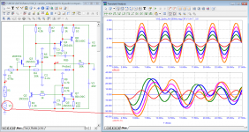
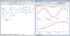
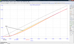
Many on the forum argued that there was no need for a time Propagation Delay study. They are sure that it is enough to have two Bode characteristics: frequency response and phase response, and from them you can easily predict the behavior of the amplifier. To once again disappoint such experts, I present the graphs of the Droup Delay (time Propagation Delay). You can see the corresponding first cicle distortion (FCD)
regards
Petr
regards
Petr
Attachments
-
 08_PCM2702_filter-Bode.png46.6 KB · Views: 88
 -
 07_SC4360_(LG-DK573)_filter-Bode.png52.6 KB · Views: 103
 -
 06_SC4398_filter-Bode.png50.4 KB · Views: 101
 -
 05_AD1853_(DAC_BRIO_3.4)-Bode.png56.8 KB · Views: 95
 -
 04_PCM63_filter-Bode.png53.1 KB · Views: 95
 -
 03_AD1853_(DAC-24)_filter-Bode.png55.1 KB · Views: 113
 -
 02_ES9018_filter-Bode.png57.1 KB · Views: 114
 -
 01_PCM63_(DAC-Igvin)_filter-Bode.png53.1 KB · Views: 115
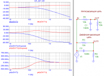
If this is the signal propagation time, then tell us how it became negative on the sixth graph. Did it appear at the output faster than it was received at the input? Has the time machine been invented yet?
Don't confuse people. The terms are similar and even the dimension is the same, but when the numerical values coincide, this does not mean that you can put an equal sign between them.
Don't confuse people. The terms are similar and even the dimension is the same, but when the numerical values coincide, this does not mean that you can put an equal sign between them.
The envelopes of the red signals (25 and 100 Hz) lead the envelopes of the input signal. But this does not mean at all that the signal at the output (red) is ahead of the input signal. The individual components of the signal are still delayed by the signal transit time. fagos, we have already considered this issue earlier. From your posts it is clear that you did not understand anything and continue to cast a shadow over the fence (продолжаешь наводить тень на плетень) in your style.
Attachments
For the integrating chain, the GD is everywhere positive, but at the output of the differentiating chain (red plot of the phase response) there is a section where the phase of the output signal begins to lead the phase of the input signal. And on the GD graph, we see that this circuit has a negative GD at these frequencies. In electronics, such a link is called "forcing".
Speaking about the frequency response and phase response, it is understood that we are dealing with a stationary harmonic signal. And the phase advance of the output signal over the phase of the input signal for these conditions is quite normal.
Speaking about the frequency response and phase response, it is understood that we are dealing with a stationary harmonic signal. And the phase advance of the output signal over the phase of the input signal for these conditions is quite normal.
Attachments
Last edited:
If you look at the frequency response and phase response, then at a frequency of 10 Hz - a ruler. But the group delay shows a negative value equal to 1.2 ms. The signal has distortions visible to the naked eye for at least 2 periods. It is easy to verify that the overtaking of the signal envelope depends on its polarity.
Attachments
However, we will continue to study the causes of distortions and the problem that Graham_Maynard was trying to draw attention to with his (FCD).
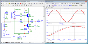
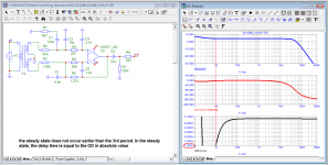
Recently simulated a 1983 Cherry circuit (60W NDFL Power Amplifier).
Here are additional test results that you won't find in any book on audio technology.
the release of the group delay outside the audio band leads to additional distortions of the first period
Recently simulated a 1983 Cherry circuit (60W NDFL Power Amplifier).
Here are additional test results that you won't find in any book on audio technology.
the release of the group delay outside the audio band leads to additional distortions of the first period
Attachments

Petr, you stopped talking about FCD some time ago, and I thought that was because you finally understood. I am disappointed that I was wrong.
I give you another tip: Build an amp in LTspice with only perfect ideal voltage and current sources and resistors and capacitors, that cannot distort, but has a representative frequency and phase response, that you can easily vary for your experiments. You still will see the same waveform at the infinitely fast start of a first cycle of course.
Think about that. It focusses on the exact issue you try to figure out, without the distracting issues of the performance of a non-ideal amplifier, allowing you to explain your ideas more sharply. Divide and conquer.
Jan
Jan, this is pointless. Did you ever try to argument with religious people? I did. And learnt my lesson.
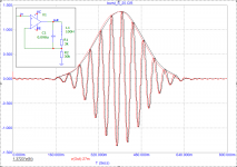
Transition point from 0VDC to first ramp-up of sinewave has discontinuity in signal derivatives. In mathematical sense, signal itself is a continuous function, but not a smooth function: at the transition point, its first derivative jumps from 0 to 2.pi.f, and its second derivative is infinite.

This is why this signal cannot exist in the real world ; real signals are always bandlimited and do not have instantaneous step functions and infinite derivatives.
Accordingly its spectrum contains frequencies up to infinity.

Testing amplifiers on signals that cannot exist is of no interest.
Band-limiting the signal (ie, making it a real signal) requires smoothing the corner, that makes all the derivatives finite, and the signal becomes smooth, ie infinitely derivable.

Here I did it with non causal FIR filter that looks into the future, so that introduces pre-ringing. Real circuits are causal, so they will introduce delay and phase shift instead, which will delay the rising edge slightly, as shown in all the pics in this topic.
To solve this non-existent distortion mechanism, I recommend OP invest in a time machine.
This is why this signal cannot exist in the real world ; real signals are always bandlimited and do not have instantaneous step functions and infinite derivatives.
Accordingly its spectrum contains frequencies up to infinity.
Testing amplifiers on signals that cannot exist is of no interest.
Band-limiting the signal (ie, making it a real signal) requires smoothing the corner, that makes all the derivatives finite, and the signal becomes smooth, ie infinitely derivable.
Here I did it with non causal FIR filter that looks into the future, so that introduces pre-ringing. Real circuits are causal, so they will introduce delay and phase shift instead, which will delay the rising edge slightly, as shown in all the pics in this topic.
To solve this non-existent distortion mechanism, I recommend OP invest in a time machine.
Peufeu, you are not the first one trying to explain it to Petr, but yours is the best I have seen.
Very clear, thank you!
Of course, Petr will not accept it because it would bring down his whole carefully constructed house of cards 😎
Jan
Very clear, thank you!
Of course, Petr will not accept it because it would bring down his whole carefully constructed house of cards 😎
Jan
- Home
- Amplifiers
- Solid State
- Musings on amp design... a thread split