Hi Damir,
And what about preamps and their GD ?
In Petr’s world it’s seemingly only the main amps that counts.
Hans
And what about preamps and their GD ?
In Petr’s world it’s seemingly only the main amps that counts.
Hans
Yes, Hans.🙁
I realy don't get what petr- is trying to explain, even if I rather like to learn something new.
I realy don't get what petr- is trying to explain, even if I rather like to learn something new.
Is this the crux?: "if the delay is related to frequency, this is the worst case. In this case, the amplitude envelopes of the signals will be violated, and the associated sound timbre" https://www.diyaudio.com/forums/sol...s-amp-design-thread-split-15.html#post6527496 Hence my question.
You did not comment post#153 https://www.diyaudio.com/forums/sol...s-amp-design-thread-split-16.html#post6527631 where I showed an amp with no LF filter and group delay of 8.7 nsec and the same amp with LP filter of 850 kHz cutoff and now with group delay of 190 nsec.
So you say that only adding input LP filter will spoil the amp completely??
You can debate whether the input low pass actually counts as part of the amp.
Consider the case where a record producer in, say, Mumbai, engages a low pass at the final result of his work. Does that all of a sodden change the amp characteristics on a reproduction amp in, say, Brussels?
It is more that a low pas changes, and is part of, the source.
Jan
Is this the crux?: "if the delay is related to frequency, this is the worst case. In this case, the amplitude envelopes of the signals will be violated, and the associated sound timbre" https://www.diyaudio.com/forums/sol...s-amp-design-thread-split-15.html#post6527496 Hence my question.
This is what we would call linear distortion, no? Change in the frequency response.
Jan
In auditory test performed by reputated institutes, the treshold of perceiving selective GD shift in frequency bands lays at several milliseconds and is the most critical in the region of 1 to 3Khz.
Below 50Hz and above 10Khz it’s even around 20msec.
Quite some difference from the nano seconds that Petr is mentioning.
But like Damir, I’m still interested to learn what impact the main amp’s GD has on the quality of the perceived sound.
A simulation producing images proves very little in that respect.
Hans
Last edited:
Any amplifier is an integrator by it's frequency-limited bandwidth.
Any synthesized single sine have unlimited derivative at it's beginning.
There are absolutely no issue to have some lag (amplitude, phase, speed or any other possible name) and the more widebandness an amp the lower this lag will be. But it is really unremovable due to primitive physics.
Any synthesized single sine have unlimited derivative at it's beginning.
There are absolutely no issue to have some lag (amplitude, phase, speed or any other possible name) and the more widebandness an amp the lower this lag will be. But it is really unremovable due to primitive physics.
Damir, I hope you understand the terms I use. As you can see, all the terms have long been known. Of the new terms, only vector error (see books by Jiri Dostala from 1981 or 1993) and velocity distortions (a term that I borrowed and Jiri Dostala and interpreted in my own way).
I hope for all the terms I have clarified in a small note
As for your two Bode plots with low pass filter on and off a delay time at 20 kHz of 8 ns is a very good parameter. But for a complete picture, a GDT graph is needed in the entire audio frequency range and then at least up to 10 MHz. GVZ equal to 8 ns indicates good speed characteristics, and SR speaks for itself. They tried to convince me here that SR does not affect anything and for an amplifier 5 V / μs is more than enough.
As for the input filter.
I already wrote that some companies began to abandon this filter, or put it with a cutoff frequency above 1 MHz. The purpose of such a filter is sometimes tried to be justified by the need to limit the supply of radio frequency signals to the input of the amplifier. On the other hand, where do they come from at the output of a signal source with an output impedance of 50 ohms. If the amplifier has TIM distortion, then no filter will help it, it just needs to be thrown into the trash.
If I were you, I would reduce the capacity by 2 times so that the total delay time does not exceed 100 ns.
If this is so important then it should be very easy to do listening test, with "standard" LP filter and the one extended upto 1 MHz. I don't believe anyone could hear any difference.
What is GVZ? This is english forum try to use standard abbreviations.
What is GVZ? This is english forum try to use standard abbreviations.
Last edited:
Damir,
The amp has no knowledge of any input filter, just like having no knowledge of your preamp, so why should it sound differently.
Your first order input filter is linear phase with a flat GD beyond 20Khz, so its only delaying the sound just like moving your chair 0,2mm back from your LS.
A clever guy is needed to come with a technical explanation why an input filter with a flat GD >20Khz could do any harm to the sound reproduction.
Hans
rather than stop floodists like you. I would be better off summarizing the results of my competition ... It would be more confusing. Although what's the point in letting him down if you don't understand what the point is
Each want to invent bicycle.
But bicycle are already invented.
Petr,
Thanks for trying to present a prove that less GD is better.
But while comparing two amps with a difference in BW of almost 20, it should not come as a surprise that the faster one has a lower GD and can follow a HF signal more faithfully.
And what you call oscillations around 350Khz of the slower one is true, but the amp is still absolutely stable and 350Khz is completely outside our auditory band.
And then your conclusion:
Particular attention should be paid to Group Delay behavior far beyond the audio range. Because .....
The greater the length of the linear section, the better. Because ....
The best option when Group Delay has a smooth decline. Because ....
A small rise in GD is allowed no earlier than at a frequency of 1 ... 2 MHz Because.....
When reading this, it becomes obvious that no statement is substantiated with any correlation to what we can hear, just simulated images that don't serve as a prove.
All you present is that an amp with a higher BW has a lower GD, completely true but not to become nervous about.
So to be more convincing, have a sonic test with a goup of people with one and the same amp with a switchable BW from 300Khz to 10Mhz.
That could bring new insights.
Sorry to be the thorn in your side, but it is with positive intentions.
Hans
Each want to invent bicycle.
But bicycle are already invented.BesPav, if you have known this for a long time, why do you put a stick in the wheels at every step?
Hans, I have repeatedly showed IMD tests and showed that an amplifier with a low and flat group delay has a lower level of distortion products in the audio band. In support of this, I cited tests of three amplifiers carried out by Bukvarev.
I am receiving letters of thanks from colleagues who used the Hafler method.
Earlier I gave a comparison of Self amps with other amps where a similar effect takes place. Therefore, I do not know what other proof is required.
Experiment yourself. Until you are convinced yourself, no one will prove anything to you.
Best regards
Petr
Last edited:
Petrov, you do not understand. What you are saying is common knowledge here, nothing new. Everybody in this thread knows this already, there is no need to support the idea or do anything else.I have repeatedly showed IMD tests and showed that an amplifier with a low and flat group delay has a lower level of distortion products in the audio band. In support of this, ...
BesPav, if you have known this for a long time, why do you put a stick in the wheels at every step?
Because you do speak about usual well-known ideas.
As wide as possible bandwidth allows to correct higher-frequencied distortion, but makes an amp more tend to oscillate under highly reactive load.
As fast as possible slew rate are usually related to underloaded high-impedance points, so less as possible feedback and one kind of distortion are traded off to another.
You rush around three pine trees and can't choose between green and hot.
Show us an OPS having more than 3 Mohm+10pF input resistance/capacitance on +-100 V rails, capable of 20 A and 100 MHz without phase reversal on straight 1nF load and you'll be our hero.
Now all your musings about nothing or already published decades ago.
BesPav, indra1 where you were before when Graham single-handedly fought off the guru attacking him. Then at least now explain this to Hans, Jan Didden and others who still don't understand ... and require proof that it turns out that everyone has long known
share the sources of your knowledge, give links to this knowledge
share the sources of your knowledge, give links to this knowledge
Last edited:
Hans, I have repeatedly showed IMD tests and showed that an amplifier with a low and flat group delay has a lower level of distortion products in the audio band. In support of this, I cited tests of three amplifiers carried out.
Best regards
Petr
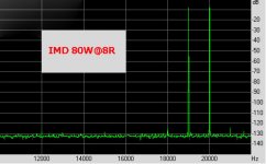
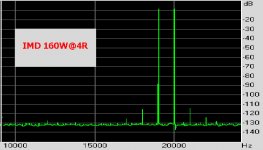
Petr,
Yes you did show images of this important IMD subject.
However, two remarks:
1) The images were simulated and not measured as far as I could see, which can make a big difference.
It could very well be a by-product of the sim program.
See the two images below of real IMD measurements of 80Watt@8R and 160Watt@4R taken from my amp.
According to your theory it should produce different noise levels but it doesn't.
2) Looking at your IMD images, all I can see is a rise in white noise, true ?
If your theory holds, white noise is harmless as long as it stays below the auditory threshold, which is the case as shown in posting #126.
Hans
Attachments
- Home
- Amplifiers
- Solid State
- Musings on amp design... a thread split