Dear Freebee,
Thank you for the suggestion.
The reason why I ask for an alternative was I was trying to buy everything from the same source, bat at the end, as I need also a couple of transformers, I use that suppler.
Thank you again
Thank you for the suggestion.
The reason why I ask for an alternative was I was trying to buy everything from the same source, bat at the end, as I need also a couple of transformers, I use that suppler.
Thank you again
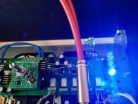
Still no working volume control 😔. The LED on the controller X5 is very faint (3.2v). On the motherboard 3 out of 5 X1 LEDs are lit and 2 X2 LEDs. No idea why 😳. Any tips or tricks to get it working?
Attachments


Systematic check all devices/boards alone/in groups.
I think you have multiple failures.
1. Check the controller seperate with power supply and check the status led and ir learning function.
2. Stack the volume board to the controller and connect to power supply and analog source signal.
3. Check the voltages on the mainboard without any other board.
I think you have multiple failures.
1. Check the controller seperate with power supply and check the status led and ir learning function.
2. Stack the volume board to the controller and connect to power supply and analog source signal.
3. Check the voltages on the mainboard without any other board.
It is necessary to understand the schematics. The answer to your question depends on J2 jumper settings.
Please check and try understand the schematic.
Daniel
Please check and try understand the schematic.
Daniel
Hi Daniel, I know about the jumper setting and that, in case of 2-3, you can feed it 15v. Unfortunately, I don't have a +- 15v dc power supply to feed it. If I were to start with the main board and be able to debug it, could I take it from there? Or should I test all boards separately?

Without cards on the mainboard, I normally measure 4.7V over the diode at the relays RY1-5. However, sometimes two relays measure resp. 2 and 3 volt, and sometimes RY 4 measures 0V. Can that be a problem with IC1? Voltages at IC10, 20, 30 and 40 measure fine.
At one stage I was able to get through to the stage where the status LED and the IR sensor were responding to the remote control (never saw the LED blink 5 times though, only 3). But I was not able to use the remote control afterwards.
To connect the controller and volume board to a seperate 15v PSU didn't work. It didn't recognize the remote control, nor did the status LED go on. Strangely, the status LED pin out changed from 3 and 5 to 5 and 8. Afterwards when I connected the controller and volume board to the main board it didn't recognise the LED pin out 3 and 5 anymore, and it would no longer recognise the remote control (status LED off).
Throughout all this, I never got any sound.
Any suggestions what to try next?
Last edited:
Yes, maybe a defective relay driverWithout cards on the mainboard, I normally measure 4.7V over the diode at the relays RY1-5. However, sometimes two relays measure resp. 2 and 3 volt, and sometimes RY 4 measures 0V. Can that be a problem with IC1? Voltages at IC10, 20, 30 and 40 measure fine.
First of all: Use the controller board seperate and startup while push the button.At one stage I was able to get through to the stage where the status LED and the IR sensor were responding to the remote control (never saw the LED blink 5 times though, only 3). But I was not able to use the remote control afterwards.
Check the status led and the remote teaching mode.
You need a controller with 100% function - otherwise it is not effective to debug the complete setup.
Regarding the controller board, does it make sense that pin 5 and 8 have stopped working (status LED)? What might have caused this to happen?
Don't believe it was due to overloading as the jumper position was 2-3 and voltage +- 15v directly taken from the main board (and correctly connected). How come that some builders use pin 3 and 5 successfully? (My controller board didn't work with pin 5 and 8, only recognised RCs with 3 and 5)
X4 measures -3.3v and 3.3v. X5 measures 3.3v at 4 different pins (pin 2, 4, 5, 8)
IC10 3.3v left and 8.79v right.
Is there anything else I should measure?
X4 measures -3.3v and 3.3v. X5 measures 3.3v at 4 different pins (pin 2, 4, 5, 8)
IC10 3.3v left and 8.79v right.
Is there anything else I should measure?
No.
First of all, you’ll need a controller with 100% function.
One more time: please check/repair the controller seperate with 3V3, led, ir receiver and rotary encoder.
First of all, you’ll need a controller with 100% function.
One more time: please check/repair the controller seperate with 3V3, led, ir receiver and rotary encoder.

So not feeding it +- 15V, but only 3.3V? External connection with jumper set to 1-2? Or is it possible to feed it through X2 with jumper set to 2-3?No.
First of all, you’ll need a controller with 100% function.
One more time: please check/repair the controller seperate with 3V3, led, ir receiver and rotary encoder.
Both controller and volume board are normally fed 3.3v AND +- 15V, through X1 and X2, when connected to the main board.
Do I need to feed the controller board both 3.3v and +- 15v?
If so, can I use X1 and X2 on the controller board?
If only 3.3v, do I use X3 and change the jumper to 1-2? Or can I also use 3.3v on X2 as input?
Do I need to feed the controller board both 3.3v and +- 15v?
If so, can I use X1 and X2 on the controller board?
If only 3.3v, do I use X3 and change the jumper to 1-2? Or can I also use 3.3v on X2 as input?
So now I should try 3.3v instead of 15v?You can use the +-15V from the mainboard with cable connection.
Or otherwise set the jumper to use the 3V3 connector.
I think you have several failures to find.
The best way is to check the units small as possible.
Please try to understand the schematic.
a) Connect >=6V to X3:1, GND to X3:2.
Set the jumper J2 to 2:3
or
b) Connect 3V3 to X3:4, GND to X3:5.
Set the jumper J2 to 1:2
a) Connect >=6V to X3:1, GND to X3:2.
Set the jumper J2 to 2:3
or
b) Connect 3V3 to X3:4, GND to X3:5.
Set the jumper J2 to 1:2