Done both methods and no luck. Status LED doesn't light up, even though it measures 3.3v on pin 5 and 8. If I am not mistaken, according to the schematic, pin 5 is plus and pin 8 negative. However, when I measure the voltage with my multimeter pin 5 is negative and pin 8 positive. Any idea what could cause this?Please try to understand the schematic.
a) Connect >=6V to X3:1, GND to X3:2.
Set the jumper J2 to 2:3
or
b) Connect 3V3 to X3:4, GND to X3:5.
Set the jumper J2 to 1:2
What voltage is X4 supposed to measure? 3.3v/0/-3.3v?
What about the voltage over the diodes?
X4 is for the ir receiver.
Did you power up the controller while push the encoder key and release the key after a short time?
Then then status led should flash.
Did you power up the controller while push the encoder key and release the key after a short time?
Then then status led should flash.
I know X4 is for the IR receiver. Is it correct that the voltage on pin 1 is plus 3.3v and on pin 3 minus 3.3v?
Status LED doesn't flash despite me holding the encoder key pressed down at start up. (I have already replaced the encoder just in case and the LED tested fine.)
What could cause the polarity of the pins to change of pin 5 and 8 on X5?
Status LED doesn't flash despite me holding the encoder key pressed down at start up. (I have already replaced the encoder just in case and the LED tested fine.)
What could cause the polarity of the pins to change of pin 5 and 8 on X5?
Hi Daniel,
Have built a single-ended version but am struggling to get it up and running.
I seam to be experiencing similar challenges to Freebee... thus, as per you recent postings, I am currently trying to get the Controller working first, before, volume board main board...
At this moment in time:
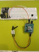
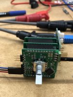
- I have Controller on its own (no volume or main boards)
- Controller is connected to 3V3 (X3:4) and GND (X3:5)
- Controller Jumper (J2) is set to 1:2
- X4 is connected to IR
- X5 is connected to LED - Anode+2k ohm Resistor (X5:5) and Cathode (X5:8)
Status:
- X4 pins2/3 measure 3.21 vdc
- No LED light or flashing
- Voltages between:
- pin1 and pin8 = 3.28
- pin6 and pin8 = 3.28
- pin7 and pin8 = 3.28
Have also held down encoder whilst powering on, holding for approx 15 seconds before releasing. No LED light/flashing.
What would you advise that I do next?
Thanks JT
Have built a single-ended version but am struggling to get it up and running.
I seam to be experiencing similar challenges to Freebee... thus, as per you recent postings, I am currently trying to get the Controller working first, before, volume board main board...
At this moment in time:
- I have Controller on its own (no volume or main boards)
- Controller is connected to 3V3 (X3:4) and GND (X3:5)
- Controller Jumper (J2) is set to 1:2
- X4 is connected to IR
- X5 is connected to LED - Anode+2k ohm Resistor (X5:5) and Cathode (X5:8)
Status:
- X4 pins2/3 measure 3.21 vdc
- No LED light or flashing
- Voltages between:
- pin1 and pin8 = 3.28
- pin6 and pin8 = 3.28
- pin7 and pin8 = 3.28
Have also held down encoder whilst powering on, holding for approx 15 seconds before releasing. No LED light/flashing.
What would you advise that I do next?
Thanks JT
Hi JT,
it seems there is any problem with the stm32.
From where do you use the 3V3?
Can you set the jumper to the other voltage configuration and feed around 7V?
I check every controller here before shipping.
Is there any solder problem?
Dan
it seems there is any problem with the stm32.
From where do you use the 3V3?
Can you set the jumper to the other voltage configuration and feed around 7V?
I check every controller here before shipping.
Is there any solder problem?
Dan
Hi Dan,
I don't think its a solder problem. I have tested for expected continuity (or no continuity) where I can and all appears to be good. Caps and 3V3 Reg also measuring as expected.
As per your suggestion:
- I have disconnected X3 from the 3V3
- Connected X1:1 to 5VDC and X1:2 to GND
- Set Controller Jumper (J2) to 2:3
Same results as before, albeit with 5VDC values.
I too think its the STM32 - I suspect that its been damaged by me and/or in transit. Equally, one of my children lost my second STM32 (for my Balanced version that I have yet to build) tidying up.... What are the chances, they never tidy up! So i do need to purchase a replacement STM32 from you anyway 🙂
Please can you PM so that I can purchase a new unbalanced-set of boards (CB,VB,MB) ands two replacement STM32 (i.e. one for this unbalanced set and one for the balanced but not built set).
Thanks JT
Attachments

@Taylorised
Is it possible that a control board has been initialized without a volume board?
Maybe not.
I did not even try it.
You may try reflow soldering the STM32.
Is it possible that a control board has been initialized without a volume board?
Maybe not.
I did not even try it.
You may try reflow soldering the STM32.
Attachments
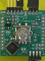
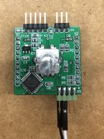
Ref Dans comment - maybe it’s a solder issue… I decided to remove/replace the controller… what the hell…. And hey presto… via X3 4+5 3.3VDC, whilst holding down the encoder… powered on… and me had a 3 flash green LED…
Happy chap here. So, I plan to switch jumper to 2-3 and test again with 5VDC via X.1+2
Assuming all still ok, I guess it’s stack controller on volume board? And what tests should I perform before moving on to adding the main board ro the unbalanced stack?
Happy chap here. So, I plan to switch jumper to 2-3 and test again with 5VDC via X.1+2
Assuming all still ok, I guess it’s stack controller on volume board? And what tests should I perform before moving on to adding the main board ro the unbalanced stack?
Have managed to get my 'unbalanced with input' version up and running 🙂 Am delighted with it - thanks @meldano.
Before I get going with my ''balanced with input' version, i have a few questions if i may:
I'm considering using a dual secondary (2x 18vdc) transformer to power my unbalanced version in my dual mono WBA18 preamp build (2x 30va transformers, 2x VRDN, 1x WBA18). Given the +15vdc feeds the Controller (3.3vdc) and the Muses (3.3 & +15vdc), would it make sense to share the secondary transform that currently only feeds the -15vdc main board input? What would i be loosing in performance? Or should i just suck it up and source a three secondries transformer?
Similarly to @namghiwook, I'm thinking that my most optimal configuration would be to connect my WBA board (R/G + L/G) inputs to X3 (RLG)?
For the 'balanced with input' version, is the following correct:
- CB
- LEFT Side:
- VB (J1 = 2-3)
- MB FULL (J1 = 1 to 2)
- RIGHT Side:
- VB (J1 = 1 to 2)
- MB PART (J1 = 1 to 2)
And, does it matter which way round you wire the +V, GND, -V inputs on the volume board (i.e. X5 is always +ve and x4 is always -ve)?
Lastly, @namghiwook, did you connect your version up to your star earth and/or did you decide to keep Earth floating?
I haven't connect any input signal ground to the earth ground. I just connected PSU ground to the earth ground.
I don't have any problem with it until now.
As you know, for balanced output from WBA18, you need 2 x WBA18 boards.
https://www.diyaudio.com/community/threads/waynes-ba-2018-linestage.329240/post-6171598
I don't have any problem with it until now.
As you know, for balanced output from WBA18, you need 2 x WBA18 boards.
https://www.diyaudio.com/community/threads/waynes-ba-2018-linestage.329240/post-6171598
Last edited:
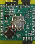
First time power up a balanced volume only version with bipolar 15 volts to X3 pin 1,2,3 and the LED (on X5 pin 5,8) do not flash during power up. Single or double presses on the encoder and the LED do not flash as well.
Hold down encoder for 15sec while powering up and still no LED flashing.
J2 jumper on main board is set for internal 3.3v, double checked everything.
Put a balanced 1kHz signal on the inputs, nothing on the output.
Need to check probably the volume boards separately. Any other ideas?
Hold down encoder for 15sec while powering up and still no LED flashing.
J2 jumper on main board is set for internal 3.3v, double checked everything.
Put a balanced 1kHz signal on the inputs, nothing on the output.
Need to check probably the volume boards separately. Any other ideas?
Attachments
Last edited:
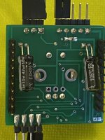
Removed the controller board from the volume boards, no change.
The LED (LTL-4213) do not flash while applying power. Also not if pressing the encoder while power up.
X4, between pin 2 and 3 measure 3.29vdc.
The LED (LTL-4213) do not flash while applying power. Also not if pressing the encoder while power up.
X4, between pin 2 and 3 measure 3.29vdc.
Attachments

Last edited:
Ok, the 2K resistor was too big, the LED was barely visible, had to turn off the lights in order to see it.
Changed to 200R and all is good now.
But the volume boards still don't do anything.
Changed to 200R and all is good now.
But the volume boards still don't do anything.
Last edited:
Do I need to setup "balanced" mode of operation via parameter 8 and the IR remote?
So far no programming has been done.
So far no programming has been done.
Last edited:
PRESS WHILE POWER UP
1. press and hold the push button
2. power up
3. wait 3 seconds
4. leave the push button
The LED will flash
1. press and hold the push button
2. power up
3. wait 3 seconds
4. leave the push button
The LED will flash
Sorry, I didn’t understand it directly.
If the LED function for mute is given, everything should be fine.
If you will use the balance mode, please have a look to the documentation.
There you can find the default value.
If the LED function for mute is given, everything should be fine.
If you will use the balance mode, please have a look to the documentation.
There you can find the default value.
I've read the documentation multiple times.
Jumpers are set for balanced and the three boards have been assembled for balanced according to the documentation.
No programming was done so far.
@meldano my question is, is programming required to change software to balanced? And is missing programming the reason why I do not get any output currently?
Last edited: