
Or did you mean to connect the controller board on a separate 5v power supply? (so NOT via the motherboard)
Yes.Or did you mean to connect the controller board on a separate 5v power supply?
After that, check all voltages on the mainboard (without any other board).
What was the reason?Now pin 6 on 2.1 main board measures almost 15v instead of 3.3v.
Not sure about REG40, the 5 LEDs in X1 are all lit. Is there a way to check the voltage after the regulator?
I have just started my version 2. It works but when i change volume its uneven in steps both with knob and remote. Set fine steps most of the time but suddenly a bigger step. And when I go back the step is at same position.
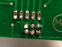
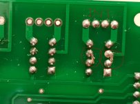
Any suggestions? Bad soldering at muses chip?
Any suggestions? Bad soldering at muses chip?
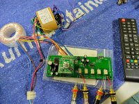
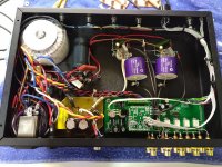
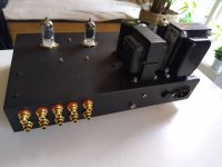
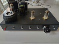
Here are pictures of a pre-stage I'm putting together. I've had an old lab pre-amp I built on for many years and constantly rebuilt. Recently, I have found a construction I like and thought of putting it in a better chassis with good volume control and input selector.
The volume is a Meldanos Muses as you can see.
The pre-stage itself is a White Catode follower with ECC802S tubes. Tube rectifier CLC-coupled and DC heaters. Also wanted to test one of the Black Gates I got a while ago.
Music is flowing and feeling well 🙂
The volume is a Meldanos Muses as you can see.
The pre-stage itself is a White Catode follower with ECC802S tubes. Tube rectifier CLC-coupled and DC heaters. Also wanted to test one of the Black Gates I got a while ago.
Music is flowing and feeling well 🙂
Attachments

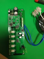
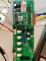
I've got a new dual secondary (18-0-0-18, 0-8) transformer, and connected it to the mainboard.
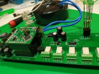
I've set the remote control functions and set the input max value to 4, then the controller board is working correctly now.
I can change input channel with my remote control and can hear tic-toc sound of relays.
The mute function is also working, so I can see the status led of the controller board being ON-OFF and can hear the tic-toc sound of relay too.
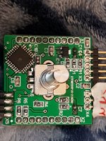
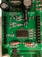
But, 5 leds of the mainboard are not working, and output sound does not exists.
I've set the jumper bridges of mainboard's X3, but it seems weired that all pins of X3 are connected(shorted).
I've checked all pin connections of Muses IC as follow as the schematic of the V2 documentation.
I've set the remote control functions and set the input max value to 4, then the controller board is working correctly now.
I can change input channel with my remote control and can hear tic-toc sound of relays.
The mute function is also working, so I can see the status led of the controller board being ON-OFF and can hear the tic-toc sound of relay too.
But, 5 leds of the mainboard are not working, and output sound does not exists.
I've set the jumper bridges of mainboard's X3, but it seems weired that all pins of X3 are connected(shorted).
I've checked all pin connections of Muses IC as follow as the schematic of the V2 documentation.
Attachments
-
 20230115_211522.jpg401.1 KB · Views: 108
 -
 20230115_213118.jpg205.1 KB · Views: 105
 -
 20230115_212804.jpg232.5 KB · Views: 103
 -
 20230115_212426.jpg393.2 KB · Views: 104
 -
 20230115_211814.jpg369.5 KB · Views: 111
 -
 20230115_211239.jpg204.9 KB · Views: 111
 -
 20230115_211425.jpg371.3 KB · Views: 112
 -
 bridge.JPG130.7 KB · Views: 111
 -
 20230115_211119.jpg389.5 KB · Views: 114