You can use the balanced mode and r/l offset.
With this workaround you can set two different single ended output stereo channels.
With this workaround you can set two different single ended output stereo channels.
How many dBs?You can use the balanced mode and r/l offset.
With this workaround you can set two different single ended output stereo channels.
Hello,
I have a V2 question. Can someone tell me which pins on X5 (controller board) the status LED should attach to? I can't find it in the documentation. Also, what value resistor should be used?
Thanks,
Alan
I have a V2 question. Can someone tell me which pins on X5 (controller board) the status LED should attach to? I can't find it in the documentation. Also, what value resistor should be used?
Thanks,
Alan
Hello,
I am finally getting around to finishing my single ended volume control with main board and control board. I haven't hooked up the RCA jack inputs yet, nor put any signal through it yet because I am unclear about a couple of things after rereading the documentation a number of times. I was able to do the infrared teach mode to setup my remote control. I am also able to set parameters by using the remote control. Now to my questions:
1) I will be using this with a standard two channel preamp with gain. I have J1 on the main board jumped from pin 1 to pin 2. Do I take the output to the preamp from X3 on the main board, or from RY5 on the main board with X3 jumpered?
2) What are the bank of 5 LEDs supposed to do? They never light up for me at all. Does this indicate a problem?
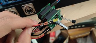
3) Are the relays silent? When I try to change channels via the remote or by the encoder, I don't hear any clicking like I would on other relay based systems I've heard. Maybe this indicates a problem. Maybe I don't have the boards wired up correctly. I'll attach a few pictures in case they may show glaring errors.
Thanks,
Alan


I am finally getting around to finishing my single ended volume control with main board and control board. I haven't hooked up the RCA jack inputs yet, nor put any signal through it yet because I am unclear about a couple of things after rereading the documentation a number of times. I was able to do the infrared teach mode to setup my remote control. I am also able to set parameters by using the remote control. Now to my questions:
1) I will be using this with a standard two channel preamp with gain. I have J1 on the main board jumped from pin 1 to pin 2. Do I take the output to the preamp from X3 on the main board, or from RY5 on the main board with X3 jumpered?
2) What are the bank of 5 LEDs supposed to do? They never light up for me at all. Does this indicate a problem?
3) Are the relays silent? When I try to change channels via the remote or by the encoder, I don't hear any clicking like I would on other relay based systems I've heard. Maybe this indicates a problem. Maybe I don't have the boards wired up correctly. I'll attach a few pictures in case they may show glaring errors.
Thanks,
Alan
Hi,
1) Yes, set X3 jumpers in your case
2) the bank of led‘s show the selected input channel an status. Did you set the parameter 4 (max input) to 4? If you set value 0, the controller didn’t send data to the mainbord.
3) the relays are very silent but you can hear them. Otherwise you can measure the coil valtage.
Daniel
Hi,
1) Yes, set X3 jumpers in your case
2) the bank of led‘s show the selected input channel an status. Did you set the parameter 4 (max input) to 4? If you set value 0, the controller didn’t send data to the mainbord.
3) the relays are very silent but you can hear them. Otherwise you can measure the coil valtage.
Daniel
Thank you for your help. I have parameter 4 set to 004, which I think is correct. I am not sure where I should measure the coil voltage. I have 5 volts on the positive side of C43. How would I go about measuring the coil voltage?
Thanks again,
Alan
Each relay coil.
Did you check the supply voltage from IC1 on mainboard?
Otherwise remove the LEDs and check the relay function again.
Did you check the supply voltage from IC1 on mainboard?
Otherwise remove the LEDs and check the relay function again.
Pin 1 and pin 8 of each relay is showing 5.01 volts.
IC1 - pin 1 is showing 3.312 volts. If there is a different pin I should check, please let me know which number.
I removed the bank of LEDs and I still don't hear any functioning of relays when I press the channel buttons or use the encoder.
Thanks
IC1 - pin 1 is showing 3.312 volts. If there is a different pin I should check, please let me know which number.
I removed the bank of LEDs and I still don't hear any functioning of relays when I press the channel buttons or use the encoder.
Thanks
Maybe a defective IC1?
Please check the I2C connection from the controller to IC1.
You can also the I2C pull up resistor values R5,6 located on the controller board.
Please check the I2C connection from the controller to IC1.
You can also the I2C pull up resistor values R5,6 located on the controller board.
Hi,
Resistors 5 and 6 on the controller are both measuring ~ 2.7k
I replaced IC1, but still no love.
Can you explain, in dummy terms, how to check the I2C connection between the controller and IC1?
Also, can I assume that because I can program the controller with the correct LED status, that my soldering of the controller chip is fine?
Thank you
Measure the connection from the controller to IC1 with your Ohm multimeter.Can you explain, in dummy terms, how to check the I2C connection between the controller and IC1?
Measure the connection from the controller to IC1 with your Ohm multimeter.
That's not quite dumb enough for me but I'll hope this is what you are looking for:
Between controller board X2 pin 9, and IC1 pin 15, I have 0.1 ohms.
Between controller board X2 pin 10, and IC1 pin 2, I have 0.2 ohms.
If I am to measure different pins, please let me know.
On the main board, my left and right audio output (by the output relay) is always shorted to ground, so I am going to reroute X4 and X5 on the volume board away from the main board, so I can feed a signal directly in and out of them. I'll use the main board as the power supply, and see if the volume portion works.
Well, I tried the above, bypassing the audio connection from the main board and routing the input and output signal via X4 and X5 on the volume board instead. I set the input channel count back to zero and the power up input channel back to zero. Unfortunately I get no sound. just a little distorted music when the power is off, which mutes completely when the power is on.
I don't see anything wrong with my build. I can swap in another muses chip, but the soldering on that looks good to me. I imagine the firmware chip is okay since I can set the remote keys and parameters.
If anyone has ideas regarding what to try next, I'll gladly entertain them. I've never had a DIY audio build failure, and I am hoping to avoid a failure here.
There are several failures.
I resolved volume control failures in 90% with better (second) muses ic soldering.
I resolved volume control failures in 90% with better (second) muses ic soldering.