Which p/n are those female headers?I hope this female header is more suitable for the second muses.
Anyone found out which are the best one to use? Thanks

Thanks for the update. You have an updated schematics? I much more prefere the Bourns encoder as well and it working i my UGS Muse preamp as well. CheersYes, it works. I use Bourns EM14 + adapter for my V2 build. Though, Bourns encoder requires 5V supply and V2 controller board works on 3.3 V. I had to add provisional 5V regulator (just 78L05 + 2 SMD ceramic capacitors).
I have an updated schematics and PCB design. Changes are minimal, 5V regulator is inserted at Bourns adapter supply line, so Muses supply (10-18V) can be used.
This thread is not right place to post details. I can attach them to PM or post at old thread, where is first adapter version, if you think they will be useful.
This thread is not right place to post details. I can attach them to PM or post at old thread, where is first adapter version, if you think they will be useful.
What is the J1 on the main board used for?
It jumpers pin 9 (A0) on the TPIC2810 to ground in its default position or sets it to 3V3.
A0 is an address input. Is this used to set the board to Left or Right in case if balanced (two board) config?
It jumpers pin 9 (A0) on the TPIC2810 to ground in its default position or sets it to 3V3.
A0 is an address input. Is this used to set the board to Left or Right in case if balanced (two board) config?
Ok.No, this jumper is not implemented.
Set it to default.
So, with balanced operation, where two main boards are required - both boards are used just bridged, in parallel, without any special addressing in the firmware? Thanks again.
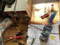
Finally after more than 2 months waiting I got my 72323 chip this morning - quick solder job, bench supply, Signal Gen and yes it runs 😎
What I especially love is that you can use different remotes for the different commands. Now I can control Volume/Mute with an Apple remote and the number keys (to program the parameters) with a Sony TV remote.
Daniel - thanks a lot!! 👍
What I especially love is that you can use different remotes for the different commands. Now I can control Volume/Mute with an Apple remote and the number keys (to program the parameters) with a Sony TV remote.
Daniel - thanks a lot!! 👍
Attachments
Guys,
anyone used to replace the TS4148 RYG diodes? These are 0805 package, which isn't easy to find and on backorder at Mouser.
All other available 4148 diodes are in different packages with slightly different dimensions.
Eventually SOD323 could fit, but isn't the same either.
anyone used to replace the TS4148 RYG diodes? These are 0805 package, which isn't easy to find and on backorder at Mouser.
All other available 4148 diodes are in different packages with slightly different dimensions.
Eventually SOD323 could fit, but isn't the same either.
Search „diode“ in this thread
https://www.diyaudio.com/community/threads/muses-volume.322983/page-18#post-6557903
https://www.diyaudio.com/community/threads/muses-volume.322983/page-18#post-6557903