What is „Pass Philosophy“, anyway?
Better sound through minimalism. e.g. No capacitor in the signal path is a good capacitor.
Superfluous is left out.
Now I would like an explanation:
Why is it important to have a particularly low-noise power supply for the Muses chip, if nobody wants to have an OpAmp in the signal path?
For testing I recommend to insert some accumulators or batteries and then compare the sound.
As a small tip: TNT-Audio has an article that shows the way to a particularly low-noise power supply (battery quality).
Simple Voltage Regulators Part 1: Noise
Enjoy the music
It is very safe and wise to keep at least 1 capacitor per channel in a DC coupled system. After the potentiometer is a good place. It also prevents damage when the MUSES would die.
That is not in the made up philosophy. There are even electrolytic caps in the Signal path of recent designs both at inputs and outputs.
Apart from that you are right. However one can be too minimalist.
Better sound through minimalism. e.g. No capacitor in the signal path is a good capacitor.
Superfluous is left out.
That is not in the made up philosophy. There are even electrolytic caps in the Signal path of recent designs both at inputs and outputs.
Apart from that you are right. However one can be too minimalist.
Last edited:
Hi,
this will work, but is completely oversized.
The Muses chip needs a maximum of 10mA per voltage, if I remember correctly.
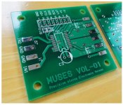
If someone is interested in my boards. There are of course improved conditions for DIY Audio members.
It is very safe and wise to keep at least 1 capacitor per channel in a DC coupled system. After the potentiometer is a good place. It also prevents damage when the MUSES would die.
That is not in the made up philosophy. There are even electrolytic caps in the Signal path of recent designs both at inputs and outputs.
Apart from that you are right. However one can be too minimalist.
Yes, that is correct. But it is also the case that he considers the capacitors necessary in such cases.
Especially since Nelson Pass is also not a capacitor freak (in my opinion in a positive sense).
Might be but I don’t care too much what others find or not find.
With asymmetric power supply the use of capacitors is almost mandatory and it again has not much to do with a made up philosophy.
Simple approach regardless of what person that says it is: best cap is no cap
With asymmetric power supply the use of capacitors is almost mandatory and it again has not much to do with a made up philosophy.
Simple approach regardless of what person that says it is: best cap is no cap
Last edited:
Muses seperate L+ R ground
Has anyone experience with seperate grounds for L and R channel?
I drawing PCB's at the moment based on the example below.
That way, I have from the source onwards, fully seperated grounds. Mono preamps and monoblock poweramps.
MUSES72320電子ボリューム基板: new_western_elec
Has anyone experience with seperate grounds for L and R channel?
I drawing PCB's at the moment based on the example below.
That way, I have from the source onwards, fully seperated grounds. Mono preamps and monoblock poweramps.
MUSES72320電子ボリューム基板: new_western_elec
Attachments
Hi Bensen,
The link gives no indication of separates grounds.?
From my point of view this is not feasible with a chip, because the power supply cannot be shared. This is intended for the complete chip and not for the individual channels.
An XLR solution with two chips would be possible, I think.
The link gives no indication of separates grounds.?
From my point of view this is not feasible with a chip, because the power supply cannot be shared. This is intended for the complete chip and not for the individual channels.
An XLR solution with two chips would be possible, I think.
Hi Bensen,
The link gives no indication of separates grounds.?
From my point of view this is not feasible with a chip, because the power supply cannot be shared. This is intended for the complete chip and not for the individual channels.
An XLR solution with two chips would be possible, I think.
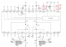
From the picture I attached (post #508), you can clearly see seperated gnd for each channel. When going through the datasheet, also here it looks if power and audio ground are not connected?? The internal pot is ground is going to L_Ref and R_Ref. I'm aware that the internal pot is made with FET's (or similar), so I would not be a surprise for me if the power and audio ground have to be connected internally in order to switch the FET's.
I don't (yet) have experience with this setup.
Attachments
Volume control or fidget spinner?
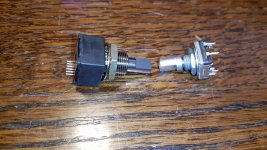
I’ve assembled Meldano’s Muses volume controller for my preamplifier. Volume control works fine but I was very unhappy with how many turns one has to make to adjust volume while changing between inputs of a different level. With original PEC-11L encoder, one full turn is 20 pulses what makes 10 dB volume change. Besides, physical sensation on the volume knob was very flimsy and unnatural, compared to the ordinary potentiometer.
So, I decided to try another encoders. There is a new encoder with ball and spring detent mechanism:
https://eu.mouser.com/ProductDetail/Bourns/PEC11H-4220F-S0024?qs=7MVldsJ5UayW2mw8xYm74g==
It has, slightly more, 24 pulses per rotation. That is better but not good enough. Physical feedback was like stepped attenuator. However, there was some play at detent neutral positions, like 1/3 of step. Other than that, it was a big improvement.
Bourns has encoders with up to 256 pulses per rotation, but with switch only up to 64 pulses.
EM14R0D-M20-L064S Bourns | Mouser Europe
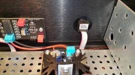
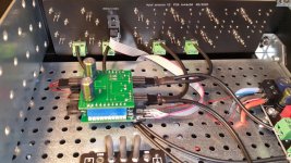
As those encodes have active outputs, simple adapter with 2 BJTs per encoder channel must be used, as controller chip works only with connecting input lines to the ground (as is case with PEC-11L type). This encoder gives excellent results. Volume control works like very fine potentiometer with 32 dB regulation per rotation and physical feedback is very good with smooth travel.
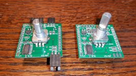
For this test, adapter was soldered directly on the controller board but I will make adapter PCB that fits to the encoder, as I like my builds to be tidy. Encoder is on the preamp front panel and is connected with flat cable to the volume control board.
I’ve assembled Meldano’s Muses volume controller for my preamplifier. Volume control works fine but I was very unhappy with how many turns one has to make to adjust volume while changing between inputs of a different level. With original PEC-11L encoder, one full turn is 20 pulses what makes 10 dB volume change. Besides, physical sensation on the volume knob was very flimsy and unnatural, compared to the ordinary potentiometer.
So, I decided to try another encoders. There is a new encoder with ball and spring detent mechanism:
https://eu.mouser.com/ProductDetail/Bourns/PEC11H-4220F-S0024?qs=7MVldsJ5UayW2mw8xYm74g==
It has, slightly more, 24 pulses per rotation. That is better but not good enough. Physical feedback was like stepped attenuator. However, there was some play at detent neutral positions, like 1/3 of step. Other than that, it was a big improvement.
Bourns has encoders with up to 256 pulses per rotation, but with switch only up to 64 pulses.
EM14R0D-M20-L064S Bourns | Mouser Europe
As those encodes have active outputs, simple adapter with 2 BJTs per encoder channel must be used, as controller chip works only with connecting input lines to the ground (as is case with PEC-11L type). This encoder gives excellent results. Volume control works like very fine potentiometer with 32 dB regulation per rotation and physical feedback is very good with smooth travel.
For this test, adapter was soldered directly on the controller board but I will make adapter PCB that fits to the encoder, as I like my builds to be tidy. Encoder is on the preamp front panel and is connected with flat cable to the volume control board.
Attachments
Hi,
thanks for your experience!
Please share the shematic to adapt the bourns.
Actually I work on a new muses board with the new Muses 72323.
Maybe I will design a new controller board with input selection option and some
other improvements.
thanks for your experience!
Please share the shematic to adapt the bourns.
Actually I work on a new muses board with the new Muses 72323.
Maybe I will design a new controller board with input selection option and some
other improvements.
Hi Meldano,
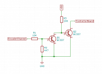
I intended to publish details along with PCB gerbers but, if someone is eager to try, here is used adapter schema for one chanell. I think it would be an excellent idea to have option for a better encoders on your implementation and wouldn’t mind if PCBs would be bigger because of that.
I intended to publish details along with PCB gerbers but, if someone is eager to try, here is used adapter schema for one chanell. I think it would be an excellent idea to have option for a better encoders on your implementation and wouldn’t mind if PCBs would be bigger because of that.
Attachments
I meant that I intended to publish schema and gerbers for other members use, not specifically for you, as you really don't need that someone else prepare gerbers for you. 🙂

Hi,
thanks for your experience!
Please share the shematic to adapt the bourns.
Actually I work on a new muses board with the new Muses 72323.
Maybe I will design a new controller board with input selection option and some
other improvements.
Hi
Yes, I'd seen the 72323 recently - what does it offer? Slightly better the / noise?
Best
Cv
MUSES72323 is an audio volume flagship product developed based on the MUSES concept. We developed it taking advantage of the circuit technology, semiconductor process technology and assembly technology that have been cultivated in the MUSES series and repeating trial listening many times.
It has high operating voltage up to ±18V, low distortion, low output noise and 0.25dB step control.
Employing external amplifiers will offer designer more flexible circuit design chance.
MUSES72323 is suitable for high-end audio equipment and professional audio equipment pursuing high performance and high quality sound.
https://www.njr.com/MUSES/series/MUSES72323.html
What about a simple volume control based around that new promising chip, but for a change one that could replace an existing volume knob in an existing amp?
Would it be that difficult to have just that chip and a very cheap conventonal pot (motorised or not) just acting as command / order, piloting the attenuation of the chip?
It could replace existing volume pots behind knobs and the volume knob position could tell where we are in terms of volume, rather than needing a display or hope for the best if you youngest has turned the endless wheel... it would also be much cheaper that way for those not needing a remote, 50$ being competitive for example.
Just thinking out loud
MFG
Claude
+1. Good way of looking at it, it would be way easier to upgrade existing gear. I don't know if they exist but an encoder with end stop just like a real potentiometer would be fine. It were your words that made me realise WHY I don't like manual operating electronic volume controls. It is exactly that "endless wheel" that feels unnatural.
A cheap potentiometer to control the chip (if possible at all) won't work OK in practice because any small scratch or bad contact may lead to unwanted side effects.
A cheap potentiometer to control the chip (if possible at all) won't work OK in practice because any small scratch or bad contact may lead to unwanted side effects.
Last edited:
- Home
- Source & Line
- Analog Line Level
- MUSES 72320 electronic volume