Every circuit has a Return Route. This is an absolute physical requirement.There is no hard and fast rule that says this is the only way to connect your source to your amp. .................
If there is no Return route then you don't have a circuit and the system will not work.
It is a "hard and fast rule".
OK, sorry about that. Your the schematic in post #6 shows a (+), (-) and ground which I interpreted as balanced inputs.What you point me out relates to a balanced line and I'm unbalanced.
Not the same scheme for hot/cold situartion versus shield.
But it also shows the ground returns for both the inputs and speakers connected together, and then connecting to power supply ground. If that is the case, it could be causing problems. Any conductor, no matter how "thick", should be seen as a low value resistor, so all return currents should be connected separately back to the main audio ground (star ground).
Mike
True. Every signal returns back to the source.Every circuit has a Return Route. This is an absolute physical requirement.
Not really. Every signal does not have to have it's own return back to the source.Every signal connection is a two wire connection.
There are no exceptions (as far as I know).
Hello
Well that's it!
No, I did not solve my problem.
But I had enough inspiration from you & related documents to realize that nothing can really improve easily.
I thought I could have an easy solution but it's not the case.
So...let's take out ALL wiring out of this and start back.
I will apply the Star Gnd concept the best I can in the present situation.
So all main points will be star grounded like the picture, below.
Notice that there is two arrows from each sub-star points(the black ovals) on each MainPSU's that reaches to the Copper-bar main Star point.
The reason is that I run two ten gauge cables from the two main caps on each MainPSU.
The inputs will be left unchanged right now but there will be "rooms" for them on the Copper bar...for an evantual Plan B, if necessary.
So here is the new schematic.
Please don't hesitate to comment as tour suggestions are welcomed.
Thanks!
Luke
PS. I'll be back to report when assembled and tested.
An externally hosted image should be here but it was not working when we last tested it.
Last edited:
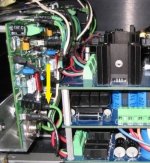
Luke, what is that green wire connected to the amp in the picture? Do all 6 amps have one of those?
Hello Pixo
The green wire you're pointing is the amp's output's on-board RC conjugate network that is getting grounded.
Note that there is two ground wire on each amp's boards: one for the Main ground and one for the RC network.
Luc
PS. Did you see my recent post about revision 3, the one just behind this one...the one that is going to keep me busy for 3 days, if not more? 😀
1. Instead of connecting the ground returns of your amplifiers to the "sub-star points" (the black ovals), take all 6 directly to the copper bar, but continue with your plan to run two ten gauge cables from the two main caps on each MainPSU. Try to keep the 10Ga cables as short as possible.
2. Remove the six ground wires that are currently hooked up from the RegPSU to the amp boards. Instead, solder one thick wire to the Ground point on the RegPSU board if possible, preferably at a point close to the supply capacitors that come after the rectifier diodes. connect that ground wire directly to the copper bar ground.
2. Remove the six ground wires that are currently hooked up from the RegPSU to the amp boards. Instead, solder one thick wire to the Ground point on the RegPSU board if possible, preferably at a point close to the supply capacitors that come after the rectifier diodes. connect that ground wire directly to the copper bar ground.
The green wire you're pointing is the amp's output's on-board RC conjugate network that is getting grounded.
Note that there is two ground wire on each amp's boards: one for the Main ground and one for the RC network.
You can run a separate wire from each amp for that on-board RC conjugate network to the copper bar Gnd. But i don't think you need wires that thick 🙂
Really? I'd like to see an electrical example of that. 😀 🙄...Not really. Every signal does not have to have it's own return back to the source.
1. Instead of connecting the ground returns of your amplifiers to the "sub-star points" (the black ovals), take all 6 directly to the copper bar, but continue with your plan to run two ten gauge cables from the two main caps on each MainPSU. Try to keep the 10Ga cables as short as possible.
2. Remove the six ground wires that are currently hooked up from the RegPSU to the amp boards. Instead, solder one thick wire to the Ground point on the RegPSU board if possible, preferably at a point close to the supply capacitors that come after the rectifier diodes. connect that ground wire directly to the copper bar ground.
Hello Pixo and thanks!
1) I thought about this, don't worry about that.The reason I did not do it the way you just descibed is that the three Gnd's shown on the schematic are actually routed this way on the PCB tracks.
They each have independant tracks that end exactly at their own pair of El-caps that ultimately all rest to "my oval point, like on the schematic".
They have been designed to have EXACTLY the same resistance each, whatever their path lenght on board.
Same thing for each Vdc+/VDC-.
And above this the each Gnd resistance is half of each Vdc+/Vdc- tracks.
I don't think that a pair of 2½ inches long of gauge 10 wire will get very far from an ideal Star point connection as far as resistance is concerned, right?
By the way...Yes...each amp are supplied by a pair of caps. So six pairs in all, three per MainPSU card.
And also, the oval point is at the middle pair of El-caps, between the three pairs.
Also the tracks are very wide, typically (±) 200 mils and thick, 3oz/Foot².
2) Pixo...look carefully. You just read bad!
What you suggest is EXACTLY what is in the schematic.
Don't forget that the "little black lines" in the boards are actually tracks, not hard wires.
And the output ground on RegPSU are NOT connected.
Luke
Really? I'd like to see an electrical example of that. 😀 🙄
Should I be wrong tu suggest the bridge amps situation where actually the hot signals don't end at their respective grounds? 🙄
Luke
Last edited:
2) Pixo...look carefully. You just read bad!
What you suggest is EXACTLY what is in the schematic.
Don't forget that the "little black lines" in the boards are actually tracks, not hard wires.
And the output ground on RegPSU are NOT connected.
I was looking at the picture of your amp internals where you had it connected it that way earlier. But now you know exactly what to do!
I don't think that a pair of 2½ inches long of gauge 10 wire will get very far from an ideal Star point connection as far as resistance is concerned, right?
Yes, 2.5 inches is not bad at all
The statement by Pixo referred to a signal current flow not returning to its source. Logically, that's absurd since a circuit is defined as continuous current flow paths within in a electrical system. There are fundamental electrical laws such as Kirchoff's that make the behaviour of these circuit currents very plain. He either misunderstands basic electronic theory or is introducing an external circuit.Should I be wrong tu suggest the bridge amps situation where actually the hot signals don't end at their respective grounds?....Luke
Bridged amplifiers still conform to the same operating principles as any other. The AC flows from its source at the power supply rail(s) to the speaker and returns via the power supply common rail. In bridge mode, the current flows also through a second amplifier following the speaker before returning to power supply common. This is somewhat like a class B output stage) with an anti-phase drive to each push-pull amplifier half.
Bridged and paralleled amplifiers - Wikipedia, the free encyclopedia
The problem with simplifications like this diagram is they assume the reader knows there is a power supply somewhere that completes the circuit. I guess that isn't always the case.
An externally hosted image should be here but it was not working when we last tested it.
I did say that.Pixo said:True. Every signal returns back to the source.AndrewT said:Every circuit has a Return Route. This is an absolute physical requirement.
I should have added "multiple signals can have a common ground return" which was the context in which it was said earlier as that is what was being discussed.Pixo said:Not really. Every signal does not have to have it's own return back to the source.AndrewT said:Every signal connection is a two wire connection.
There are no exceptions (as far as I know).
I don't understand why people get hung up on a single post and assume theories of their own. It helps to read the entire conversation before coming to conclusions about things.
I do not assume theories, nor hypotheses of my own, unless I state such in the pre-amble..................I don't understand why people get hung up on a single post and assume theories of their own.................
If I state a FACT, then I mean it and it is never an assumption of my own.
A circuit allows current to flow from a voltage Source and that current MUST RETURN to that Source. This is physical FACT.
Originally Posted by Pixo View Post
...Not really. Every signal does not have to have it's own return back to the source.
+1Really? I'd like to see an electrical example of that......
Man, I don't get it. Is this problem solved yet, and if so what was the fix? I am having noise problems in diy preamps and sometimes when I induce a ground loop it improves noise?!?! Doesn't anyone know the most common ground loop, noise inducing, rookie mistake for wiring grounds? Grounds are madeningly frustrating.
Luke123,
All the input signal gnds should be brought back to the input ground only, to each and every pcb. However to be more sure, you can use 2+1shield cable and connect the shield at the individual ground on the pcb end only. Shield remains open near the connector side.
I would like to see the ground copper layout of your psu pcbs.
Did you know that any psu connection more than 2 inches needs its own bypass caps.
Gajanan Phadte
Luke
There is one thing that is not shown in your diagram and a possible source of problems, and that is the source.
If you are joining up all the shields at source or input connector, it creates another, new loop between each amp board, the common shield at source/connector and the star ground. One possible solution is to use a very small ground lift resistor that swamps the wire resistance. 0.1 to 0.5 ohms should be enough. This is to be inserted at each amp's entry for the shield.
- Status
- Not open for further replies.
- Home
- Amplifiers
- Solid State
- Multichannel amplifier internal ground loop