Looking at the picture of your amp on post #28, i see multiple green wires coming from each board from the point which looks like the ground connection for each amplifier module. Where does each one go to?
Hello Pixo and thanks!
OK.
There are one pair of 16Ga green wires that goes to the MainsPSU Gnd and another pair of Ga20 wires that goes to the RegPSU GND.
Doubling wires meant for me having one ground for V+ and another one for V-.
For present stuation right now I guess it's overkill!😱
Luke
Generally, for a system with balanced inputs the ground should only connect the chassis' of the separate components together, and not involve the active electronics at all. So IMHO it might be a problem.
Mike
Mike
ok, before you go about fiddling with the wires again, i suggest you test this out:
Use your "Y splitter to 6" adapter from the signal generator and hook up all the signal inputs. But for the signal ground/return, just connect ONE signal return point of ONE connector back to your signal generator.
Test and let me know your results.
Use your "Y splitter to 6" adapter from the signal generator and hook up all the signal inputs. But for the signal ground/return, just connect ONE signal return point of ONE connector back to your signal generator.
Test and let me know your results.
The pic showing the layout automatically generates excessive LOOPs when ever any two inputs are connected to a common ground back at the Source.
This LOOP can be broken by separating the input Signal Return from the Amplifier Power Ground.
That breaks the LOOP.
But you must reference the Signal Return to the amplifier's Reference Ground. This is where the Disconnecting Network comes in.
D.Self describes it. Leach describes it. But they use a sole resistor. For added Safety I now use a pair of inverse parallel power diodes and a resistor.
I repeatedly remind Builders that a multiple Channel amplifiers MUST use separate Signal Return from the Power Ground.
Hello Andrew...good to see you back on this!
1) Amplifier's disconnecting network...What do you mean by this, because I made a search in D.Self's PDF book, "Audio Power amplifier design handbook" and nothing about "disconnecting network.
Is it equivalent to my Earth/Gnd switch coupling network with Resitor and cap?
Can you show me something, a picture or else, to show me your point, please?
2) In examining his book I fell on this circuit of his, page 459...Figure 16.1 which I can't send to forum because of possible rights enfrangements, naturally.
So I ghuess you have this book that you can refere yourself for sake of this discussion.
And I found his schematic and noticed the way he handles input Gnd and Earth versus Star points...
Ground from input connector is connected to amp circuit's input Gnd... AND...goes to Chassis which is connected to AC Earth.
What is particular is that Star is not connected to chassis elsewhere at all and make me conclude that input Gnd is the only point to chassis/Earth.
Mmmmmm...could it be my "Holly Graaled" solution?
I'll try it to see...
Luke
Last edited:
By the way....
Sorry if some of my answers could come late but I'm telling you...
Right now reading, refering, understanding, studying, implementing and ...answering is real full time job!
Thanks for helping!
Luke
Sorry if some of my answers could come late but I'm telling you...
Right now reading, refering, understanding, studying, implementing and ...answering is real full time job!
Thanks for helping!
An externally hosted image should be here but it was not working when we last tested it.
Luke
Adding a low value resistor is a common practice. ETI 480 input has 10 ohms to ground.
Gajanan Phadte
Gananan...this has been done with no success in my case.
Luke
You can see how I solve problem on diy Hiraga amplifier. Hiraga-brum - Stranica 3 - Solid State - diyAudio.rs
Impuls
I went to your link but the langages used are really " foreign" for me.
Anyway the first schematic you seem to relate for, Post #58, shows a power grounf/earth scheme...without discussing the input and Amp's circuit reality where my problem takes place.
The next schematic shows a Gnd/Earth circuit about the same as mine wirthout the bridge.
I have to point out that EACH of my amp's channels shows very good noise figures at the point where one has to be in a completely silent environnment and listen to noise with a tweeter stuck in the ear to hear a "glimpse of a hiss and very small ac harmonics".
It's only when you plug more than one input that the Buzz problem arrises.
Farther in your link, Post #68, there is a scheme I tested last friday, seven days ago that a certain poster named "Dig01" posted few years ago from another site.
Thanks!
Luke
The Shield must continue the TWO WIRE connection all the way from the Source to the amp Input.
You must NOT break the Shield connection. It is part of the RETURN route and MUST be maintained.
Andrew
What do you mean?
If it's about two wires, meaning a balanced line...my case is not a balanced line but unbalanced.
And if your meaning of two wire is "Shield and signal wire", it's not broken in any of my schematics of mine.
Luke
Generally, for a system with balanced inputs the ground should only connect the chassis' of the separate components together, and not involve the active electronics at all. So IMHO it might be a problem.
Mike
Hello Mike
If you can...
Sending a schematic to show your point would be interessting.
Luc
ok, before you go about fiddling with the wires again, i suggest you test this out:
Use your "Y splitter to 6" adapter from the signal generator and hook up all the signal inputs. But for the signal ground/return, just connect ONE signal return point of ONE connector back to your signal generator.
Test and let me know your results.
Pixo
You ask me to connect the Y6 to all amps and connect only one shield to Gen.
Since the Y6 is already soldered ...
Could it be the same if I use the Y6 to all amps but one one Shield connected to one amp's input?
Anyway I just did it and there is noise, unacceptable noise. Nothing changed in fact.
Level stays the same if I short the single RCA at the other part of the Y to simulate a low source Z.
Luke
Luke123 not connect all six grounds ti one point, just pull together all six signal cables to the star point, not connect this, and then pull one by one together with power ground to each amp separately. It means that You have from the star ground six signal cables to back side of the amp, and six pairs Signal cable+ground wire. It looks like star with legs
Every signal connection is a two wire connection.
The source pushes the electrons out to the load and the load returns the electrons back to the Source.
ALL the current that comes from the Source RETURNS to the Source.
There are no exceptions (as far as I know). This applies to all signal connections between modules, even unbal AND bal.
If you use a screen as the second wire of the two wire pair then that Screen is the signal RETURN. It MUST connect at the Load end AND it MUST connect at the send end.
This applies to low level signals, like RF in aerial coaxials and in high level signals, like speakers and all the other inter module connections.
If you don't use coax and instead use two discrete wires it is best to twist these Flow and Return Pairs. Alternatively, one can use close coupled Flow and Return Pairs, as is seen in a two core mains cable (that is rarely twisted).
A Final Reminder:
Do NOT break a two wire Flow and Return connection.
Last edited:
Hello Mike
What you point me out relates to a balanced line and I'm unbalanced.
Not the same scheme for hot/cold situartion versus shield.
I noticed in the Neutrik part of the doc that you point out that some of the solution looks kind of extreme to be applied and relates in my point only to some of very low output sensor or acquisition probes.
My god, my situation should have much more simple solution as I have to deal with line levels.
I'm definitely have a stupid error of mine in my setup...but where?
Thanks.
Luke
Every signal connection is a two wire connection.
The source pushes the electrons out to the load and the load returns the electrons back to the Source.
ALL the current that comes from the Source RETURNS to the Source.
There are no exceptions (as far as I know). This applies to all signal connections between modules, even unbal AND bal.
If you use a screen as the second wire of the two wire pair then that Screen is the signal RETURN. It MUST connect at the Load end AND it MUST connect at the send end.
This applies to low level signals, like RF in aerial coaxials and in high level signals, like speakers and all the other inter module connections.
If you don't use coax and instead use two discrete wires it is best to twist these Flow and Return Pairs. Alternatively, one can use close coupled Flow and Return Pairs, as is seen in a two core mains cable (that is rarely twisted).
A Final Reminder:
Do NOT break a two wire Flow and Return connection.
There is no hard and fast rule that says this is the only way to connect your source to your amp. I run a 10 foot cable from my 3-way analog crossover to each of my two speaker towers that have four amplifiers running a tweet-mid-woof-woof combo 🙂 Each cable has three 24AWG wires taken from a CAT5 LAN cable, running inside a shield taken from a coax cable. Cross talk might be an issue, not that i can hear any. But i've never had problems with grounding. When connecting six signal lines from one source to one amplifier, one signal return, preferably shielded, is all you need, provided you did everything else right.
one signal return, preferably shielded, is all you need, provided you did everything else right.
By this i mean a ground return that also serves as a shield to the signal lines.
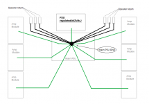
Luke, here is how you would route the ground connections of each module/unit/block in your amplifier to resemble a star ground.
Hello again Pixo!
1) If I compare your DRW to my revised Schematic of Post #45, page 5, you have common point with mine which is the Star to Amps path.
2) And now, for your speaker part in your drawing, I'm curious about something.
Does it matter by the fact that a speaker's terminal could be fed by a PSU shared copper track of 2.5 inches long on a PCBoard, if anyway...
• it is passive thus non active...
• it's balanced by nature...
• it deals with high-level signals...
• it is of low impedance ...
• it does not care at all to have a grounded or non-grounded fed signal...
• and this on any of its terminal...
• it does not need at all to be shielded...
...?
3) Do I assume your inputs Gnd are connected at the inputs of amps and share the Amp track up to the Star point
4) Finally does your suggestion is based on my drawing post #45 which has a pair of Power PSU, a regulated PSU, both on a common star point?
Luke
Well, yours looks a whole lot more complicated than my drawing 🙂1) If I compare your DRW to my revised Schematic of Post #45, page 5, you have common point with mine which is the Star to Amps path.
2) And now, for your speaker part in your drawing, I'm curious about something.
Does it matter by the fact that a speaker's terminal could be fed by a PSU shared copper track of 2.5 inches long on a PCBoard, if anyway...
• it is passive thus non active...
• it's balanced by nature...
• it deals with high-level signals...
• it is of low impedance ...
• it does not care at all to have a grounded or non-grounded fed signal...
• and this on any of its terminal...
• it does not need at all to be shielded...
Can you post some photos of your main power supply section? And i don't see the large supply smoothing capacitors after the transformers. Are they hidden?
In your case, what i'd do is have a single ground for signal return and connect it to the main PSU Gnd terminal, preferably through a 4.7 ohm resistor while the six signal lines will be connected to one amplifier each. It will work, because the amplifiers will be grounded to the main PSU.3) Do I assume your inputs Gnd are connected at the inputs of amps and share the Amp track up to the Star point
A pair of power PSUs is not the problem - how it's wired is the problem. And i see a lot of green wires exiting the regulated PSU board, while ideally i'd only have a single thick wire connecting the regulated PSU board ground to the main PSU ground.4) Finally does your suggestion is based on my drawing post #45 which has a pair of Power PSU, a regulated PSU, both on a common star point?
Don't worry about RF interference, mains interference, twisting, shielding, etc. Those are the least of your problems right now.
Well, yours looks a whole lot more complicated than my drawing 🙂
Can you post some photos of your main power supply section? And i don't see the large supply smoothing capacitors after the transformers. Are they hidden?
In your case, what i'd do is have a single ground for signal return and connect it to the main PSU Gnd terminal, preferably through a 4.7 ohm resistor while the six signal lines will be connected to one amplifier each. It will work, because the amplifiers will be grounded to the main PSU.
A pair of power PSUs is not the problem - how it's wired is the problem. And i see a lot of green wires exiting the regulated PSU board, while ideally i'd only have a single thick wire connecting the regulated PSU board ground to the main PSU ground.
Don't worry about RF interference, mains interference, twisting, shielding, etc. Those are the least of your problems right now.
Pixo
1) Well yes, mine looks more complicated but I don't have the choice...One extra MainPSU, RegPSU...that's life.
2) Some infos in pictures...mainPSU during assembly, MainPSUsch, RegPSUsch.
Note that starpoints on MainPSU are at C10-C11 and on RegPSU at C4-C8.
Here we go...
An externally hosted image should be here but it was not working when we last tested it.
An externally hosted image should be here but it was not working when we last tested it.
An externally hosted image should be here but it was not working when we last tested it.
3) I've done this your way as stated in previous posts but not with coupling resistors.
4) Now for Gnd speaker lines I'm a bit skeptic in one sense but open for surprise in the other.
PSUs are funny beasts sometimes!
Maybe I could try it but it involves a certain amount of hours...
and maybe tomorrow...
For now I'm kind of "done". Mucho done.
Thanks
Luke
Last edited:
- Status
- Not open for further replies.
- Home
- Amplifiers
- Solid State
- Multichannel amplifier internal ground loop