I'm thinking...
Please do .... ;-)
You could try the pentode stripped to triode and check. This is the easiest experiment.
Please do .... ;-)
You could try the pentode stripped to triode and check. This is the easiest experiment.
Please visit my post for Mu Follower analysis:
Mu Follower Analysis
If Pentode is on top, the screen voltage should be reference to it's cathode, if Vg2=100V, it's better to have a separate supply for this with negative connected to cathode and positive connect to screen via a resistor. So if you take apart the 2 tubes, as shown in the analysis, the top pentode now is ground cathode amp, so the screen is reference to cathode too.
Attachments
This all very nice, but it is not build....
I have "build" many High Voltage amps on a computer, but until you have not smelled the burned components you will not know how it sounds ;-)
I have "build" many High Voltage amps on a computer, but until you have not smelled the burned components you will not know how it sounds ;-)
Thank you Kmoon for your explanations. However, Lampie's approach was to make me understand things on my own. I have to do the measurements in AC. I also understood that: if I had a greater resistance than 3k (in this case here around 60kΩ maybe) less current will flow. Moreover the 47uf has at best a reactance of 170 Ω at 20Hz, it is not chosen much. In my case, in static: the current is 11mA. The voltage between the anode and the cathode is 144V. Which gives 13k. Alternately on a 13k // 3k ~ 2.5k ...
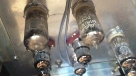
Lampie, I already shotgunned a 6f12p in this thread some time ago. XDXDXD
(A Gu807 too with my plasma tweeters)
(A Gu807 too with my plasma tweeters)
Last edited:
Yes, i want you to find your own way and understand the fundamental idea of this topology.
Naturally all help is welcome as long as it does not divert from this topology !
Marco, did you try the "triode way" (just disconnect all components under rsc, you can leave rsc as protection of G2) ?
If you protect G1 with a diode to C then you can save some tubes in the future...
I usually use PCF80 tubes as these are easy to find (usually for free) and do the same here.
Last edited:
Lampie ,not yet but i will do it soon.
I will try too without zener and a big resistor.(and a lower capacitor)
I will try too without zener and a big resistor.(and a lower capacitor)
I just realise what is wrong with the Pentode Mu follower.
If you know simulation try to see if your schematics can even sim?! But I thank you for posting...you need to put thing right, I hope simulation can be helpful.
If you know simulation try to see if your schematics can even sim?! But I thank you for posting...you need to put thing right, I hope simulation can be helpful.
I just realise what is wrong with the Pentode Mu follower.
If you know simulation try to see if your schematics can even sim?! But I thank you for posting...you need to put thing right, I hope simulation can be helpful.
Simulations can be tricky as in many cases the model is not provided for tubes when used above ground level !
I just realise what is wrong with the Pentode Mu follower.
If you know simulation try to see if your schematics can even sim?! But I thank you for posting...you need to put thing right, I hope simulation can be helpful.
simulation is a very useful tool which allows a good approach
simulation is a very useful tool which allows a good approach
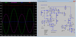
According to Koonw this can't even be simulated... So the simulator is Kaputt !
The simulator will just quit if the schematics is far from accurate, i.e it quits because there is no point carry on.. it wouldn't waste your time or sometimes it takes for ever. So you have to make different circuits, it is yourself the master, not the destroyer.
The simulator is Kaputt !!!
Check your settings (Gear and Transients) !
Plus put a small 0.1 Ohm resistor in series with any diode !
Check your settings (Gear and Transients) !
Plus put a small 0.1 Ohm resistor in series with any diode !
Any resistor or zener connected this way will shunt the output so the bottom waveform is clipped earlier than expected. This is a known problem for a long time. For pentode to work properly the only way is to float the screen. The sim helps to reveal this problem. The shunting effect will depend on the pentode tube in use, logically a bigger one will be less affected as internal resistance is lower than smaller one: e.g EL84 vs 6F12p.Thank you Kmoon for your explanations. However, Lampie's approach was to make me understand things on my own. I have to do the measurements in AC. I also understood that: if I had a greater resistance than 3k (in this case here around 60kΩ maybe) less current will flow. Moreover the 47uf has at best a reactance of 170 Ω at 20Hz, it is not chosen much. In my case, in static: the current is 11mA. The voltage between the anode and the cathode is 144V. Which gives 13k. Alternately on a 13k // 3k ~ 2.5k ...
I do not need a simulation to see the issue at hand here, just common sense.... (see entry #67 and #69)
Plus already have given a working solution to this issue in #80.
Plus already have given a working solution to this issue in #80.
Last edited:
- Home
- Amplifiers
- Tubes / Valves
- Mu stage driver