Hello,
I just read the thread:
0.005% distortion: Two MOSFETs in series; it gets complicated.
0.018% distortion: one MOSFET only.
What does this represent compared to the triode itself ?! Let's keep it simple: a single well-chosen MOSFET seems a good option. The goal is therefore to find a MOSFET with high transconductance at low current without having to create a complicated circuit.
Mu follower is push pull design, each has different Gm. Balance can be adjusted with Ru (Rp), so it depends a lot on the accuracy of the design. It's well cover in these 2 articles:
http://www.bartola.co.uk/valves/wp-content/uploads/2018/12/DHT-Preamps-ETF2018-final-notes.pdf
http://www.bartola.co.uk/valves/wp-content/uploads/2018/12/DHT-Preamps-ETF2018-final.pdf
http://www.bartola.co.uk/valves/wp-content/uploads/2018/12/DHT-Preamps-ETF2018-final-notes.pdf
http://www.bartola.co.uk/valves/wp-content/uploads/2018/12/DHT-Preamps-ETF2018-final.pdf
Thanks for the pdf files but i can't read them with my phone.
I just read that Irf710 needs a lot of curent to work well.
So i ban it.
I just read that Irf710 needs a lot of curent to work well.
So i ban it.
If you want a single MOSFET hybrid Mu stage I recommend similar sch as attached:
1) Top device is CSS as well as Mu follower (classic tube).
2) It therefore isolated the lower tube from output.
3) The upper device handles all the output current as it's single ended.
4) It can handle different load value down to 20K without any change of components.
1) Top device is CSS as well as Mu follower (classic tube).
2) It therefore isolated the lower tube from output.
3) The upper device handles all the output current as it's single ended.
4) It can handle different load value down to 20K without any change of components.
Attachments
Hello.
Thanks for your post.
DN2540 is a good MOSFET and cheap.
Perhaps this one too :IXTP02N120P.
So finally and after a few reading a two mosfets circuit should be better.
But for understand the circuit i prefer to start with one MOSFET.
I have 6n8s 2p29l and 6P21S tubes.
In a few time i will order mosfets and buy a good fonctions generator.So i could share experimentations.
Last edited:
Hello.
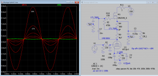
Remake of 6f12p mu follower for a phono preamp output stage.
I think that there is less distortion at an higher current than 5 mA.I choose 11mA.
I made several tries with a 3,3kΩ; 3kΩ ;then 2kΩ load.
and 100v then 120v at screen.Here is the result:
 [/url][/IMG]
 [/url][/IMG]
 [/url][/IMG]
Remake of 6f12p mu follower for a phono preamp output stage.
I think that there is less distortion at an higher current than 5 mA.I choose 11mA.
I made several tries with a 3,3kΩ; 3kΩ ;then 2kΩ load.
and 100v then 120v at screen.Here is the result:
Hi Marco, that is very interesting, did you really measure it?
This is no Mu Follower at all....
This is no Mu Follower at all....
Last edited:
Hello Lampie,
Happy to read you here and hope all is fine for you.
Indeed it is not the mu stage of Allan Kimmel.
However, Valve wizard calls it mu follower.
The Valve Wizard -Mu Follower
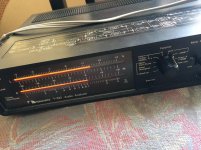
I had already built it for 5ma. (Look at the thread) It was working fine but I think it's better around 11ma. The photos show the diagram with the tensions that I measured as well as my construction.
Happy to read you here and hope all is fine for you.
Indeed it is not the mu stage of Allan Kimmel.
However, Valve wizard calls it mu follower.
The Valve Wizard -Mu Follower
I had already built it for 5ma. (Look at the thread) It was working fine but I think it's better around 11ma. The photos show the diagram with the tensions that I measured as well as my construction.
Hi Marco,
I am fine thank you !
Let me explain....
The Zener is paralelled by a capacitor right? For AC voltages this is a short !
The impedance of the pentode is now < 3.9k if you like it or not.
"Valve Wizard" didn't use pentodes....
I am fine thank you !
Let me explain....
The Zener is paralelled by a capacitor right? For AC voltages this is a short !
The impedance of the pentode is now < 3.9k if you like it or not.
"Valve Wizard" didn't use pentodes....
Last edited:
Valve Wizard" n'a pas utilisé de pentodes...
Yes but I tried and it works.
The zener sets the screen voltage at 125v (I'll take pictures with my multimeter tomorrow if you want). The screen voltage is thus regulated. Better than a simple resistor, right? Compare with Kimmel's mu stage, there is also a capacitor which is connected in the same way. Then I took a value that I had on hand, but I just checked 47uf and 3.3kΩ gives 1 Hz so it's good.
So what is it ?
How we call it ?
The Marco follower ?
But if you will help me to improve it I am happy, however I am limited by the current 12 ma maximum
How we call it ?
The Marco follower ?
But if you will help me to improve it I am happy, however I am limited by the current 12 ma maximum
Last edited:
The resistor value is too low... lower then the tube itself ... Better to remove the tube and use only the resistor, this is more linear...
Or use a seperate voltage but do not paralell the tube with a low value resistor...
Or use a seperate voltage but do not paralell the tube with a low value resistor...
Last edited:


Please understand what "Mu Follower" means and then check if this circuit complies...
And if you do understand it then you will find that even Alan Kimmel's version is flawed (in his pentode implementation).
And if you do understand it then you will find that even Alan Kimmel's version is flawed (in his pentode implementation).
Last edited:
Hello, indeed, I already have trouble understanding a cathode follower and even more so with a pentode. However what I have built seems to work well and I understand things better with practice.
Gain=200
 [/url][/IMG]
At 100hz with my chinese 10€ functions generator
 [/url][/IMG]
Gain=200
At 100hz with my chinese 10€ functions generator
Last edited:
A Cathode follower is different from a current source.
A current source should represent an indefinite resistive load... not 3.9K or even 100K but at least 1M or so....
As long as this requirement is not met you will end up with a standard resistive load amp...
A cathode follower needs to follow what is offered and also would like to have an indefinite resistive load (current source again) on its cathode...
Can you measure distortion ?
Attachments
Last edited:
I don't have a device that can measure distortion.
I just mesured voltages in my device.
 [/url][/IMG]
But I could to send you 6f12p and diodes if you want
I just mesured voltages in my device.
But I could to send you 6f12p and diodes if you want
Last edited:
- Home
- Amplifiers
- Tubes / Valves
- Mu stage driver