Cal is calibrate and is sometimes VAR (variable) and is generally a center pot on the timebase and vertical amplifier controls.
https://bama.edebris.com/download/hitachi/v1100a/HittachiV-1100A Oscilloscope Operation Manual.pdf
https://bama.edebris.com/download/hitachi/v1100a/HittachiV-1100A Oscilloscope Operation Manual.pdf
When I'm probing for that drive signal with the caps from gate to source I am still getting that funky waveform on my scope. I'm just kind of confused why it's not a few volts dc there to open the gate?
Which funky waveform?
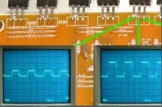
You picked one of the oddball power supplies. Below, you can see two sets of waveforms. The one that swings above and below ground is the MTX type of drive (from a transformer). The other that's all above ground is, by far, the most common and possibly what you expect.
You picked one of the oddball power supplies. Below, you can see two sets of waveforms. The one that swings above and below ground is the MTX type of drive (from a transformer). The other that's all above ground is, by far, the most common and possibly what you expect.
Attachments

You multimeter doesn't have the bandwidth to measure the ACV.
Did you reset the var controls back to the fully clockwise position?
Did you reset the var controls back to the fully clockwise position?
I did. Still trying to figure out this differential setup. I do have thos fets in the amp. I will read through this user manual you sent me a link too (thank you). I downloaded it and will read through it when I can.
For class D amplifiers, differential mode is huge. For your scope, it should be easy to do. Let me know if you have questions.
This is definitely the first class d amp I've even looked at. Much different then class a and class ab. So what am I supposed to be adjusting here? I can pull the the channel 2 position knob to invert the 2nd channel but cant seem to get in differetial mode with any of the variable adjustments.
Attachments
With one channel/probe, if you touch the 12v terminal of the power supply, the trace should deflect up ~2.2 divisions with the vertical amp on 5v/div.
With the other channel, touching the same point, the trace should deflect down the same amount.
If you touch both to the 12v+ terminal at the same time, the trace should not deflect.
Do not ground the 3rd terminal of the FET with the FETs installed. That was only for testing the drive signal with no FETs installed.
Right. They both deflect the 2.2 divisions in opposite directions showing 12v, but when touching them both to 12v at the same time they do the same thing. I understand the idea behind differential so I understand what I'm looking for here but cant seem to figure it out on the scope. Also yes the source of the fets are not grounded.
I figured it out with your question. If I hit add channel 2 the channel 1 button pops out. So I had hit alternate so both channels would be shown. If I hit add 1 and 2 at the same time they both are displayed. Sorry about that, user error no doubt. So yes now when touching both probes to a 12v source there is no deflection like it should be.
If you only need one channel, you can leave the scope precisely as it is.
The reason it's important for class D amps is because the high-side FETs are typically N-channel and their entire drive is swinging rail to rail. The only way to confirm that they have the proper drive with a mains powered scope is to use differential mode.
At this point, is the amp powered up with the FETs in the circuit?
Is it producing rail voltage?
I didn't power it up yet. What size fuse should I use being a round one? Wired directly to a 12v battery?
Why can't you use one of your smaller (10 amp?) power supplies?
Remember, all semis tightly clamped to the heatsink.
Remember, all semis tightly clamped to the heatsink.
I did just power it up on that power supply. It seems to be pulling about 3 to 4 amps for a minute then the amp starts making some strange sound and it shuts down. The led kind of shutters with the screech sound. Nothing seemed to get hot on the amplifier in that time.
Does the supply stop producing drive from pins 8 and 11 of the TLx94?
Is the jumper on the cap on or off?
Does the 12v supply voltage remain at the original voltage or is it dragged down considerably.
Is the jumper on the cap on or off?
Does the 12v supply voltage remain at the original voltage or is it dragged down considerably.
The voltage did seem to be getting dragged down. I set the hp at 12v. When I connected the remote wire I looked at the hp and iirc it was at about 8 to 10 volts and a few amps. That's when it made a whining sound as it powered down (most likely from undevoltage) I think the hp doesnt like the load on it before I even hook up the remote wire. The jumper is still on the cap. It didnt stay powered up long enough for me to take any voltages.
- Home
- General Interest
- Car Audio
- MTX 1501D repair help