That may be too low in resistance. The carbon pile type would be adjustable.
I'm not sure that you'll be able to charge the rail caps with the CCS FET on the board. You may have to desolder and lift the center terminal to allow the caps to charge incrementally.
I'm not sure that you'll be able to charge the rail caps with the CCS FET on the board. You may have to desolder and lift the center terminal to allow the caps to charge incrementally.
I could reinstall the 4 fets and give it a shot. I'm sure the resistance of this load tester most likely rises if it gets warm from current flowing through it. Why wouldn't the caps charge with low resistance source?. They are supposed charge when the 0 guage wire is wired to the amp that has even less resistance.
That tester probably wouldn't limit much of anything. A 10ft piece of 20g wire would limit more.
The limiting is needed here because there may be a problem and I don't want to destroy any more parts. The excessive current draw could be due to capacitor inrush or some other problem.
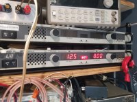
Do you have a DC supply that has internal limiting or is possibly simply limited in its capacity (10 amp power supply).
The limiting is needed here because there may be a problem and I don't want to destroy any more parts. The excessive current draw could be due to capacitor inrush or some other problem.
Do you have a DC supply that has internal limiting or is possibly simply limited in its capacity (10 amp power supply).
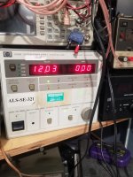
Use that. There is no way to damage the FETs if they're clamped to the heatsink with 10 amps of current.

Neither of my power supplies will let me get the voltage that high. Seems there is some built in protection that I dont fully understand. Either of these power supplies have ever done this to me before. Somthing about this amp they dont like. I did notice when I do get low voltage and a few amps going into this amp the clamp fet483 warms up quickly while the clamp on fet 437 (bank they were exploded in) doesnt change temp at all. Il have to get a big resistor I guess.
When you were checking the drive, did you do so (with the 0.01uf cap) for both banks of PS FETs?
Did you check the rectifiers?
If the drive is OK and the rectifiers are OK, you may need to remove the rectifiers (or at least desolder one terminal) and see if it will power up that way.
Did you check the rectifiers?
If the drive is OK and the rectifiers are OK, you may need to remove the rectifiers (or at least desolder one terminal) and see if it will power up that way.
Last edited:
So now when checking the drive on the bank of fets that wernt blown now has 12vdc. The other bank has no voltage. And no last night when I installed the cap it was only on bank where nothing blew up. It is strange tho I feel like everytime I take measurements from anywhere they have changed since the last time. When I checked the rectifier yesterday I swore they read on my meter just like I would expect but now they are reading kind of funny. If i knew how they were situated that would help with measurements. I think r436 is either coming off the board and going bad. It no longer has co tact with the drive and is reading 40ohms across it. That prolly explains the drive voltage being 12v. Il replace it. Its prolly just getting sick of all the heat next to it from soldering and desoldering
Last edited:
After replacing the drive resistor the 12vdc is gone and while scoping the drive signal I get the same funky looking waveform i had last night on both banks
Are these fets garbage or usable? I normally only get components from mouser or another reputable source because I'm worried about counterfeits. I dont think these are counterfeit, I just never used a bojack tranny. I've used there resistor kits with no issues.
Attachments
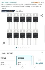
Buy from a known reputable distributor. You don't need any more unknowns.
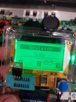
Did you check the FETs with this tester when you stated that they were OK?
Did you check the FETs with this tester when you stated that they were OK?
Ok. Il get them from mouser in my next order. Yes them did read good yesterday. I think I accidentally reversed the polarity of the power wires with a 10 amp fuse inline. The fuse popped so I didnt even get the remote wired up. I went to replace it with a 15 amp and realized I just hooked them up backwards. I had a long day yesterday before talking to you. But hey that's how it goes. That is likely what took that fet out I'd imagine. Maybe not but I think maybe soo.
I'm also going to order some drive resistors. I know the value but do you happen to know the watt rating on them?
Order the resistors by size (0805?). Measure them with a dial caliper.
Before you order, go back through all of the steps and confirm that you have good drive (using the loading capacitor) for both banks of PS FETs.
You may also want to enable the output stage and confirm that the op-amps have ±15v on the power supply terminals and the two optocouplers have 19v across terminals 5 and 8 (do NOT let the probes slip when checking this).
Do you know how to use your scope in differential mode?
Do you have any FETs in stock?
I will check for good drive. I dont have differential probes and do not know how to use that mode. I allways superimpose the waveforms. I do have some fets on hand but not many. Most of my stock is all bipolar transistors. I will dig around and check for some.
You don't need a differential probe. All you need is two standard probes.
The Z44s are OK for testing. Remember to clamp everything.
Check the items listed above before installing the PS FETs.
Re-disable the output section before installing and powering with the Z44s.
A differential input uses two inputs to produce a single waveform. The simplest way to get a differential input is to use a differential probe. A differential probe has two signal leads and a mixer amplifier built into it. It feeds the scope a normal signal (a composite of the two signals input into the differential probe). The problem with differential probes is that they're expensive.
The alternative is to use two scope probes and and both inputs of your oscilloscope. This is how you have to set up your scope:
Two probes
Both scope inputs used
Input set to add
Both channels set to DC coupling
Both channels set to 'cal'.
Both vertical amps set to the same voltage
Ch2 input set to invert
Bandwidth limited (works best for most measurements in car amps)
Trace aligned to the reference line on the scope's display
Ground leads for both probes connected together (not always necessary)
After setting up the scope, you need to confirm that it's working as it should. With the vertical amp set to 5v/div, touching the probe that's connected to Ch1 to the positive terminal of your 12v power supply should make the trace deflect about 2.5 divisions up from the reference (like it always does, seen below). Doing the same with the probe connected to Ch2 should make the trace deflect down about 2.5 divisions. Touching both probes to the positive terminal of the 12v power supply should cause no deflection. If it does, something isn't right.
I know that this may not be as simple as the isolated scope but if you take the time to learn it one time (even if it takes an hour or more of your time), you have that knowledge and this tool to use for the rest of the time you need to use a scope. Using the analog scope will give you much larger and cleaner waveforms.
I dont think my old scope has that calculate (cal) option. Of course I can invert one channel. Is there any other way they might have labeled it?
- Home
- General Interest
- Car Audio
- MTX 1501D repair help