No the amp didnt power up till I hooked up the remote wire. But there is some draw beforehand. Not a ton but the amp definitely loads up some capacitors or somthing just hooking the positive and negative leads up. At least it appears to. If I wire a battery to just the positive and negative lead there is a slight arc at contact. That's how I've been testing voltages with the fets removed
It has a bank of primary filter capacitors that charge when you connect only B+ and ground.
Do you have another small supply other than the HP?
If not, try the 15 amp fuse with the battery. You can probably go to a 20 with glass fuses.
On my 25 amp bench supply, these amps will draw enough current (for a fraction of a second) to slam the needle on the amp meter against it's stop.
If you want to test without the rail caps charging, you could desolder one terminal of each of the 4 rectifiers. That would leave the FETs driving the transformer and nothing else. That may allow the HP to work.
Rectifiers in the circuit?
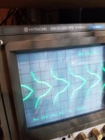
The waveform will change because it's a regulated circuit and the duty cycle changes to maintain the target rail voltage.
If you monitor the pin 8/11 waveform and vary the 12v input voltage, you can see the duty cycle change.
The waveform will change because it's a regulated circuit and the duty cycle changes to maintain the target rail voltage.
If you monitor the pin 8/11 waveform and vary the 12v input voltage, you can see the duty cycle change.
Yes the rectifier are in circuit.
That is cool. It is more involved then I thought. It makes perfect sense as it is a automobile amplifer and will be used in less then ideal conditions voltage wise.
That is cool. It is more involved then I thought. It makes perfect sense as it is a automobile amplifer and will be used in less then ideal conditions voltage wise.
Did you check the other voltages in the amp?
I'd like to make sure that they're all correct before enabling the output stage.
I'd like to make sure that they're all correct before enabling the output stage.
I did get a wave off pin 8 (didnt probe 11) but I'm not sure what I'm looking for. The voltage at battery is not getting dragged down considerably. What other voltages should I check?
The pin 8 was just for knowledge. You'd vary the 12v supply voltage to see the difference.
Op-amps, pins 4 and 8 voltage with ground as reference?
Optocouplers, DCV across pins 5 and 8 (don't slip).
Op-amps, pins 4 and 8 voltage with ground as reference?
Optocouplers, DCV across pins 5 and 8 (don't slip).
that didnt go well. I measured the octocouplers and had 19.6v on one and checked the other one was 20.1. I thought that was strange and measured again and slipped. The squealing noise on start up now is constant. Damn I should have found a better way to measure that. Pretty sure I shorted pin 7 and 8 of the octocoupler closer to the output transistors.
Did any of the output FETs short (check all lead configurations).
20v is OK. The voltage varies due to tolerances in components in the regulator circuits.
20v is OK. The voltage varies due to tolerances in components in the regulator circuits.
The outputs didnt short. But the squealing from whatever it is dont sound good. It comes and goes with the power led.
Hopefully, only the opto failed.
Having the output stage disabled may have saved the outputs.
Do you see a short pin 5 to 6/7 or from pin 8 to 6/7?
If/when you do this again, probe from the outside of the pins, against the body of the IC. 2. Sharpen the probes.
Having the output stage disabled may have saved the outputs.
Do you see a short pin 5 to 6/7 or from pin 8 to 6/7?
If/when you do this again, probe from the outside of the pins, against the body of the IC. 2. Sharpen the probes.
It seems the 2 fets in the one bank are shorted all 3 legs. Unless its somthing downstream. All 3 legs are dead shorted. The bank that originally had the good ones. I can replace those 2 with 2 of the originals.
What is the part number on the FETs that failed?
Don't try to power up again.
You need to confirm which opto failed and to determine if the regulator for that circuit failed. You'll have to remove the opto that's defective.
Don't try to power up again.
You need to confirm which opto failed and to determine if the regulator for that circuit failed. You'll have to remove the opto that's defective.
They failed when tightly clamped to the heatsink?
Did you confirm that one opto was reading different than the other (5-6/7 or 8-6/7)?
Did you confirm that one opto was reading different than the other (5-6/7 or 8-6/7)?
- Home
- General Interest
- Car Audio
- MTX 1501D repair help