With no remote, I wouldn't expect any noise.
Do you see drive pulses from pins 8 or 11 of the TLx94?
Do you see drive pulses from pins 8 or 11 of the TLx94?
I didnt test for any voltages. I hooked the power wire up and the amp started making a sizzling sound so I pulled the power. Yes with no remote wire.
I'm looking for what could be causing the noise, if you can't identify it. That's why I asked about pins 8 and 11.
I cant identify it without powering it back up and then I'm not sure I still can. Ir may go away when the caps charge up but I dont remmeber hearing it before.
You'll have to power it up as you did when you heard the noise to help identify.eliminate the possible source.

Ok so when I hooked up the power leads it didnt make any noise. Then when i hooked the remote wire up it's making a screeching sound. I powered if up two times for about 5 seconds each time. I ran around it with my ir thermometer. I did see some heat on the bank of output transistors wich are now clamped down . It is the bank of fets that the octocoupler I shortened last night is associated with. The bank closer to the octocouplers.
Drive pulses on 8/11?
Rail voltage being produced?
Are the outputs actually heating or something in the area?
Rail voltage being produced?
Are the outputs actually heating or something in the area?
I fired it back up and there is about a half a volt on each rail. It was still screeching and then the fuse popped. It's a 15 amp fuse (same size I've been power it up with). It didnt run long but seen the rectifier bank getting warm. More particularly d446 and/or d447
I need something more definitive.
What's the resistance across the B+ and ground terminals of the amp?
Pull the PS FETs and see if it blows a fuse.
If not, does it make any strange noise?
Does it produce any drive from the TLx94?
What's the resistance across the B+ and ground terminals of the amp?
Pull the PS FETs and see if it blows a fuse.
If not, does it make any strange noise?
Does it produce any drive from the TLx94?
The resistance between +and - was 215ohms. After pulling ps fets it is 1 megaohm. It is not blowing fuses when powered up. It is not making any noise at all. The fets all test good in my tester. Checking drive at the ps fet sockets I get a signal but not the same as I was getting. Here is a picture.
Attachments
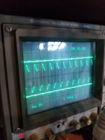
Is the scope triggering properly?
Is this with remote applied?
Is this waveform with the loading capacitor?
Is this with remote applied?
Is this waveform with the loading capacitor?
This is with remote, amp powered on. This is without the loading cap. I played with the scope to get the best possible image.
215 to 1M appears that the FETs were either partially on/conducting or leaking.
Check them with a multimeter.
Use the loading cap and confirm that both drive signals look the same for both banks of FETs.
With no power applied, what's the resistance from the gate to the source for the PS FETs?
Check them with a multimeter.
Use the loading cap and confirm that both drive signals look the same for both banks of FETs.
With no power applied, what's the resistance from the gate to the source for the PS FETs?
The fets checked out with dmm
I installed loading caps and both drive signals look like they should.
The resistance between gate and source on both banks is 38.3 ohms
I installed loading caps and both drive signals look like they should.
The resistance between gate and source on both banks is 38.3 ohms
With no remote, does the drive signal stop?
Are there any areas on the transformer windings that appear to have been damaged, overheated?
Do you have a split ±15v (or any voltage) power supply that could be used as a low-voltage rail to test the amp?
Are there any areas on the transformer windings that appear to have been damaged, overheated?
Do you have a split ±15v (or any voltage) power supply that could be used as a low-voltage rail to test the amp?
The drive signal does stop without remote hooked up. The transformer doesnt looked to be damaged from overheating. I do have many smaller power supplies I'm sure I can get set up to power thr rails. Also when peeking around I see someone has removed q240 wich I read people do to disable the protection circuit for running lower them recommended impedence subs.
Do you see any voltage on the remote terminal of the amp when you connect only B+ and ground?
DCV on pin 4 of the TLx94 IC with no remote?
You can read? It's very rare that you find anyone who will read anything that they don't absolutely have to read. For most, if it's not in video form, they're not interested.
DCV on pin 4 of the TLx94 IC with no remote?
You can read? It's very rare that you find anyone who will read anything that they don't absolutely have to read. For most, if it's not in video form, they're not interested.
The remote terminal has no voltage when amplifier does. Pin 4 of the tl494c has exactly 5v. I can read, the issue is how much of the information I can retain simply by reading it. I am a hands on learner. I usually do allright when its somthing I'm interested in. I'm definitely interested In understanding these class d amplifiers.
- Home
- General Interest
- Car Audio
- MTX 1501D repair help