hehe that's exactly what I thought before I first placed them, but that's exactly what the wife doesn't want ~ she likes open plan living room ....
I will try it though see if it makes any difference cheers
I will try it though see if it makes any difference cheers
I figure the eff. port is ~47 mm diameter x lv = 206 mm -with the length being seen about 15% longer due to slot loading at bottom surface. Can you put this in your box tuning program again?
I figure the eff. port is ~47 mm diameter x lv = 206 mm -with the length being seen about 15% longer due to slot loading at bottom surface. Can you put this in your box tuning program again?
infinia can you explain this a bit more? are you saying that the port length is larger than it should be?
what is "eef." and "slot loading at the bottom surface" ? sorry I don't understand

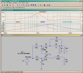
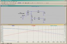
This example should help you
niiice
have you modelled the crossover only or crossover and speakers in this example?
Just the electrical model with amp/wire resitance and drivers simple HF loading ie Re, & Le
( not acoustic or LF resonances)
The effective port looks slightly longer because the slot is using the bottom surface of the cab.
( not acoustic or LF resonances)
The effective port looks slightly longer because the slot is using the bottom surface of the cab.
Last edited:
I see I see
Thanks for the clarification, I will check port dimensions to see if they match the madisound spec.
Cheers!
Thanks for the clarification, I will check port dimensions to see if they match the madisound spec.
Cheers!
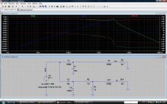
I have simulated the speakers and woofers.
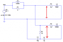
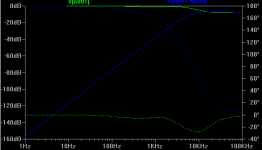
The green line shows the woofer voltage db and the blue is the tweeter.
It's a strange result. Tweeter looks fine but the woofer line doesn't dip enough.
Any ideas?
I have also shown where I have taken the voltage across (red arrows), is that correct?
The green line shows the woofer voltage db and the blue is the tweeter.
It's a strange result. Tweeter looks fine but the woofer line doesn't dip enough.
Any ideas?
I have also shown where I have taken the voltage across (red arrows), is that correct?
Attachments
I also did a sensitivity analysis on the 1.5R resistor
I tried 5 10 and 15 ohm and things don't change significantly
finally i tried changing the polarity of the woofer and then the tweeter, but nothing changes
....🙁
I tried 5 10 and 15 ohm and things don't change significantly
finally i tried changing the polarity of the woofer and then the tweeter, but nothing changes
....🙁
Something's wrong then.
Take the outputs across Re only. Unfortunately the way you have got things arranged mean you need to use V differences of nodes, I used ground to my advantage. Also you have to show the sum of Low and High passes to see the effect of polarity.
So you can rearrange stuff in your drawing with ground or play the polarity bookkeeping game.
What does Madisound say about the schematic drawing as you depicted it?
Hi there.
I sent the question to Madisound yesterday, so will see what they say.
Also I have designed a 2nd order crossover and simulated with the driver models and seems fine.
I am sure the madisound crossover i have got is wrong.
I sent the question to Madisound yesterday, so will see what they say.
Also I have designed a 2nd order crossover and simulated with the driver models and seems fine.
I am sure the madisound crossover i have got is wrong.
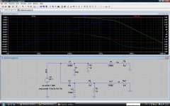
Shown with tweeter polarity reversed.
Note the charts need to be normalized for driver sensitivity differences to determine the crossover point.
So if the tweeter is higher by 6 dB then multiply HP side by 2.
Note the charts need to be normalized for driver sensitivity differences to determine the crossover point.
So if the tweeter is higher by 6 dB then multiply HP side by 2.
Attachments
Last edited:
Yup higher order filters along with moving the crossover down should get rid of the paper sound ie cone breakup. I would recommend the 2way crossover topology used by the guru Dr. Joe D'Apolitto see Usher 701 check the example I posted (see post 23 in this thread). You can
probably re-use some of your parts.
BTW he is the Guy who invented MTM http://www.parts-express.com/projectshowcase/usher701/designer.cfm
probably re-use some of your parts.
BTW he is the Guy who invented MTM http://www.parts-express.com/projectshowcase/usher701/designer.cfm
Last edited:
infinia thank you very much for doing this
i can see where i was wrong now in my circuit
i think what i will do next is reverse the woofer polarity (cables) and see how it sounds
if sound is still no good we will see what madisound recommend
if no luck i will go ahead replace the crossover with a 2nd order one and decrease the xo frequency to around 2000 - 2500 Hz.
The simulation seems to show that the crossover point is at around 4000Hz currently which is too high.
cheers mate
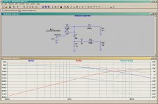
This is a 2nd order crossover at 2000 Hz.
It also includes L-pad on the tweeter to attenuate it by 3 db.
I also included an resistor in parallel with the woofer to get rid of a small peak in the crossover frequency
Does this network look okay?
Any ideas or guidelines in the net on how to calculate BSC?
Evan
It also includes L-pad on the tweeter to attenuate it by 3 db.
I also included an resistor in parallel with the woofer to get rid of a small peak in the crossover frequency
Does this network look okay?
Any ideas or guidelines in the net on how to calculate BSC?
Evan
Attachments
...and this is the crossover by selecting component values so that I can salvage some parts from the old crossover...
I found that this increased the xo frequency a bit and that a 20ohm resistor in parallel with the woofer is needed to smooth that peak a bit
I found that this increased the xo frequency a bit and that a 20ohm resistor in parallel with the woofer is needed to smooth that peak a bit
Attachments

Madisound confirmed the crossover scheme and resulting response curve from LEAP. No surprises there.
Hi chatziva
I'm impressed with the speed you picked-up LTspice.
About your xover low-pass peaking, it is Q related using 2nd order filters. Are you adding the inductors Rdc in the model? Also it can be minimized by altering the ratio of L/C. Additionally the load(Re) is being decoupled with your woofers higher value of Le too, so its better to have more L on the input (or adding small R in series with C to fine tune). Also note your lack of BSC, which is also helped by using a larger value L on the LP filter. (hint look at the shareware edge program, to pick initial values for L.) Why don't you tweak the values of the Usher 701 topology to your cabinet and drivers.
Are you going to build a bigger box and re-tune for more bass?
Hint>
You really s/b cascading your LP filter to the mid-bass drivers natural LP roll-off, off-axis at 45 degrees or so. That is how I decide where to cross and what Q to use. In other words, I want both LP filters to overlap somewhat and the total response to be Linkwitz-Riley 4th order.
- Status
- Not open for further replies.
- Home
- Loudspeakers
- Multi-Way
- MTM design