glt said:Russ,
Thanks for your listening impressions. I did order the opus upgrade thinking that with the '741, Wolfson is realizing all of their long experience in developing DACs. May I ask what filter did you use and what's the sampling rate (I'm assuming that you are using the Metronome)... thanks
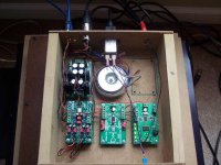
Right now I am just running the DAC in a little test rig box I threw together (all from scrap). It's running in hardware mode (right now, not for long), so my filter options are limited to low,medium,high sample rates.
Later today I will be throwing in a controller with a VFD display to handle volume control and setup. The input will be IR(RC5) and rotary encoder.
I am using the Metronome at 96khz. So I have the filter set to medium sample rate.
I am also find that I really like the anti clipping filter!!! It makes some poorly recorded CDs (way too hot) sound much better. And it does not seem to negatively impact the good ones. Basically it just pads to the digital signal down 2db prior to the analog stage, at the digital filter.
The opus is under the IVY upside down so that all the I2S are short and straight. This is an excellent way to layout the modules.
Also note I am only using one PS. 🙂 this was done for expediency more than anything, but I have proven it works very well.
Here is a picture, don't laugh too hard. 😉
Cheers!
Russ
Attachments
Hi Russ,
I've seen that wooden box configuration many times before (maybe a different wooden box 🙂). I thought the chip would support several filter modes at a specific sampling rate. From the data sheet p42, with pin 4 you can select the following filter responses: Pin4 (FSEL/DINR): Digital Filter Selection: for 32/44.1/48KHz: 0=Response1, 1=Response 4, Z=Response 5; for 88.2/96,176.4/192KHz: 0=Response3, 1=Response 1, Z=Response 2.
Thanks
Hi glt,
Yes you very well may have seen this box before I have used it for other prototype work recently. 🙂
Ah yes, it is true you can choose between 3 filter modes. I just have not done so yet. I have been more busy getting the controller up and working. 😉 I don't plan on using hardware mode for much longer.
For now I have that switch open so I am using filter response 2. 🙂
I will probably play with it a bit later.
Cheers!
Russ
Hi Russ,
Good to hear. I hope the OPUS "uber controller" will be available first (before the Buffalo uber controller 🙂). VFDs are kind of expensive. I've purchased 2x16 OLEDs from ebay which are reasonably priced. I suppose you will support 2byX character displays. Thanks.
Good to hear. I hope the OPUS "uber controller" will be available first (before the Buffalo uber controller 🙂). VFDs are kind of expensive. I've purchased 2x16 OLEDs from ebay which are reasonably priced. I suppose you will support 2byX character displays. Thanks.
"VFDs are kind of expensive ..."
Yea, but nothing else looks as good and you only need to buy the one for your project. 😀
Yea, but nothing else looks as good and you only need to buy the one for your project. 😀
The display we have selected is not that expensive (<$40 IIRC). The key to it is that it has an I2C interface rather than the quasi-standard serial/parallel interface. If you find another I2C based display, we can probably confirm that it will work.
And it does look really really good.
And it does look really really good.
Re: Listening note...
Yes, I'd like to try the WM8741. Hoever, one issue I have is that the WM8804 front end won't handle 176.4k in hardware mode.
Have you now solved this? I listen to hirez a lot; upsampled or native.
Fred
Russ White said:OK I want to clear up a misconception. 🙂
The WM8741 is really well done. It hits all the right buttons. I have been listening to it for a while now, and I will not give it up. I have been A/B testing it with the buffalo and while they do both sound distinct, I would not say either has an advantage. Except in one area. The Opus is far less finicky. 🙂
Yes, I'd like to try the WM8741. Hoever, one issue I have is that the WM8804 front end won't handle 176.4k in hardware mode.
Have you now solved this? I listen to hirez a lot; upsampled or native.
Fred
Yes, I'd like to try the WM8741. Hoever, one issue I have is that the WM8804 front end won't handle 176.4k in hardware mode.
Have you now solved this? I listen to hirez a lot; upsampled or native.
We have a new receiver/MUX coming out based on the CS8416, which will natively support 176.4K without any special treatment. It will also sport 4 SP/DIF inputs (1 optionally balanced/AES). It will output S/PDIF and I2S. All S/PDIF ports are transformer coupled. Source selection is done via a four pin header, allowing either uC control or a simple switch.
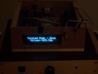
Nearly done implementing the controller.
Again ignore the ugly box it just there to get the thing working. 🙂
I love the VFD. The picture actually does not do it justice. Blame the photographer. 🙂
The controller is just a modified old Joshua Tree controller.
All the hardware is setup now, I just need to write some firmware tomorrow.
Cheers!
Russ
Attachments

Very nice. The OLED displays are also nice, here is picture http://picasaweb.google.com/bugandang/Share?authkey=r8sXtF_sJhY
The one I'm using is based on the Hitachi interface, so it will not work with the OPUS controller.
The one I'm using is based on the Hitachi interface, so it will not work with the OPUS controller.
We originally planned on using OLED, but no one actually manufactures them any more (OLED character displays that is), and we can only find them in small pools of old stock.
As an example: http://www.osddisplays.com/pled.php
Also, even with the Hitachi controller, the exact pin out of the interface changes depending on manufacturer. So, if we had to pick something, I2C seemed like the way to go, as it freed up more controller pins for other purposes.
This is only AC1, however... no telling what we might change in the future.
Hi Brian,
I got mine from ebay -Sure Electronics. Seem to be plentiful from those guys. All the "cheap" (from a couple of dollars, up) LCDs I've seen are based on the Hitachi interface
I got mine from ebay -Sure Electronics. Seem to be plentiful from those guys. All the "cheap" (from a couple of dollars, up) LCDs I've seen are based on the Hitachi interface
glt said:Hi Brian,
I got mine from ebay -Sure Electronics. Seem to be plentiful from those guys. All the "cheap" (from a couple of dollars, up) LCDs I've seen are based on the Hitachi interface
I you look back through the thread a bit you will see I have used PLEDs and love them visually. 🙂
The problem is you never know when their stock will go away.
Nobody (that I know of) is making PLED character displays anymore. So any suppliers like Sure are likely selling NOS. When its gone its gone. Now I could be wrong here, but I have contacted a couple manufacturers and they told me as much. 🙂
Plus I just like the VFD much better. 🙂 Its a bigger brighter display for not much more money. Well worth it.
The SPI interface on the VFD is much easier to work with. 🙂
Cheers!
Russ
Russ White said:
Plus I just like the VFD much better. 🙂 Its a bigger brighter display for not much more money. Well worth it.
It does look nice! From the photo it's a little difficult to judge the size. Is it about 1.25 inches in height? It would be nice if it fits the face of a 1U box. [1.25" would be ~ideal, no?]
The next trick is to make it *smart* as well as pretty! 😉
Opus-related question since I'm posting:
You report that WM8741 has good low pass filtering. Nice! I was hoping to run Opus outputs directly into the high impedance front end TXD within my TXOverture amps - balanced all the way. In your test setup, is the IVY enhancing the sonics of the Opus by adding more filtering or perhaps 'just' buffering? If possible I'd like to avoid a second THS4131 buffer and stay as simple as possible. [My interconnect situation is good - 12" to 16" shielded with gold contacts.] What do you suggest?
TIA,
Frank in Minneapolis
This is the type VFD module it is.
2 x 20 146.0 x 43.0 x 19.2
It made by Newhaven Display.
Ifyou going direct to a TXD you don't need an IVY at all. In fact I would just go direct as you mentioned. I have in fact done this with excellent results.
Cheers!
Russ
2 x 20 146.0 x 43.0 x 19.2
It made by Newhaven Display.
Ifyou going direct to a TXD you don't need an IVY at all. In fact I would just go direct as you mentioned. I have in fact done this with excellent results.
Cheers!
Russ
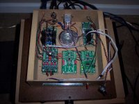
Up and Running, And Version 2.0 errata
OK I finally got my firmware written. And it worked first shot!. 😀
Now in doing all this I found two issues with the silk screen on the OPUS version 2.0 boards. Neither are very serious, but need to be noted.
I added terminal blocks along with the pin headers pads for a few of what I expected would be frequently used signals. A couple of them are incorrectly labeled.
The terminal mark "ML" is actually "MUTE".
The terminal marked "MUTE" is actually "IWO" or buffered data output.
I will add an errata to the manual, and correct things on the next revision.
Neither should pose a problem as long as the user is aware of the issue.
Now for the working Opus:
It has rotary encode and infrared input.
Controls are volume,mute, and balance (very simple add .5db at a time to either side).
I only used 256 of the 1024 steps available for .5 db from 0db to 127.5db. 🙂
Cheers!
Russ
Attachments
Russ,
What resistor and cap values did you settle on for IVY when used with the WM8741 version of OPUS?
What resistor and cap values did you settle on for IVY when used with the WM8741 version of OPUS?
Carl_Huff said:Russ,
What resistor and cap values did you settle on for IVY when used with the WM8741 version of OPUS?
This is the first I have been able to try it, so for now I am using 2K at the inputs and 2.21K feedback so that I get just a little bit of gain.
This gives me an input impedance of 2K which is an easy load for the DAC.
You could also use 1K at the input and feedback. I am not sure which is better.
You don't need any filter caps at all on the balanced end. In fact I think it sounds better without them.
I have not done any serious listening yet with the SE outputs, just balanced. So I am not sure if the LM4562 would benefit from a some filtering.
One listening note. I *think* (can't be sure yet) that I do prefer filter response 2 for all sample rates. Trying to find a way to describe why...
Cheers!
Russ
- Home
- More Vendors...
- Twisted Pear
- Mr White's "Opus", designing a simple balanced DAC