Uncluttered purist version without coupling caps...
You managed to use the UniversalAmp2, well done.
To answer your question, noise from a fet starts with 1/f noise at as from some point it becomes flat.
Where noise becomes 3 dB above the flat noise, because of the 1/f noise, is called the knee point, or Enk. In case of the Opa1652 Enk=400Hz while the plateau is at En=3.8e-9nV/rtHz.
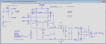
A number of remarks on your latest .asc file
1) U1 and U2, being the largest noise contributors are still the LT1056.
These are the most important ones to change to OPA1652
2) To play with noise figures, I have parametrizes En and Enk.
So to get a feeling for their sensitivity, by changing this parameter all six opamps are changed.
3) You used a 100pF cap around U3/U5. This is more than needed. In this configuration 47pF is enough, but I changed the gain by 6 dB for the first stage and reduced the gain for the second stage by 6dB, giving another reduction in total noise.
With R6/R9 now 2K instead of 1K these caps can be reduced to 27pF.
At the same time R7 is changed from 400R in 800R.
4) You still used different values for the INA, these should absolutely be the same, see explanation in posting #11467.
The other thing that can't be done is to place a cap over the feedback resistor. If needed, you would also have to place a cap par, to R28, to keep the balance.
But those caps would have to be within 0.1% not to destroy CMRR, which is a bridge too far.
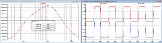
5) But in the first imaqe below you can see in blue when applying a square wave, that 27pF is o.k. for the first stage, and that you won't even need a cap for the INA in red.
6) I used a more down to earth 2N2222 instead if the transistor you used, it makes no difference in total noise.
7) As you can see, A-weighted noise is now 45uV instead of the previous 131uV with LT1056 + the lower first gain, a huge drop in noise of 9.3dB !
EIN is therefore with a gain of 62.4dB, a whopping 0.24nV/rtHz with 0R source.
Hans
.
Attachments
The general textbook message is resistor value ratios have to be equal
(you can set up the subtracting circuit with any gain different from 1).
Others still have to demonstrate which resistor scaling would be optimum
for "equal input impedance / current" on the positive and negative side.
Andreas did you miss Frans' post? His sim clearly shows equal currents with unequal (factor 2, not 3) resistors.
Edit: post 11466 https://www.diyaudio.com/forums/analogue-source/154210-mpp-1147.html#post6816016
Jan
Thank you very much Hans
I am still digesting the modifications you made on the laplace transform as now we do not get antiriaa response in the output.
You chose to have 54dB gain in the 1st stage..... it seems high to me considering the signal is not RIAA treated there and we reduce headroom this way... But maybe this is not an issue with MC carts.
Perfect.... I would build it if I had some IF3602 at hand 🙂
how many k170 would I need to replace one IF3602 ?
I can not see what is going on in this picture and what kind of part "E1" is.
LMLTUFY:
Syntax: Exxx n+ n- nc+ nc- <gain>
This circuit element asserts an output voltage between the nodes n+ and n- that depends on the input voltage between nodes nc+ and nc-. This is a linearly dependent source specified solely by a constant gain.
Frans has set the gain to 1E6 to emulate an opamp.
Warning: if you are going to ask what is happening there, I will quote the typical answer of a patent lawyer: this is 'obvious for those experienced in the trade ' 😎
Edit: you can see in that graph that the currents through the two resistors (I think it's the red and blue I(R1) and I(R4) are identical in magnitude.
Jan
Last edited:
Hi Ricardo,
I just added a 1x source which you can switch with the Laplace source by shifting one or the other to drive the amp.
So your Laplace is still there. Be sure the one that’s not in use is connected to the 3 gnd points.
The SK170 has twice the 3602 noise, so theoretically you would need 8 of them to replace the dual 3602.
Biggest problem will be the matching, so I would either advise to use 12 matched devices or 6 per side to get some averaging between their individual differences.
But maybe Joachim is willing to part from one of his 3602 stock for a reasonable price.
Hans
P.s. the amp can still process 50mV@20Khz, which seems more than adequate.
Jan, I am not into sim (I asked for a formula - aren't we engineers ?)
and I do not know what LMLTUFY is.
"My favourite programming language is solder " - not sure who invented this phrase ..
"I think it's the red and blue" , yes, I do not know, the curves are there but without
any description, so who knows ?
For me sim does not prove anything, but who am I to argue.
and I do not know what LMLTUFY is.
"My favourite programming language is solder " - not sure who invented this phrase ..
"I think it's the red and blue" , yes, I do not know, the curves are there but without
any description, so who knows ?
For me sim does not prove anything, but who am I to argue.
differential amp
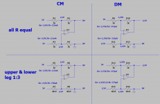
as, all, I have made a sketch for all four cases:
-common mode and differential mode
-equal resistors and unequal resistors 1:3,3 ratio
equal Rs: equal common mode input impedance on both inputs
Rs on the noninverting input 3,3 times higher: equal differential mode impedance on both inputs
as, all, I have made a sketch for all four cases:
-common mode and differential mode
-equal resistors and unequal resistors 1:3,3 ratio
equal Rs: equal common mode input impedance on both inputs
Rs on the noninverting input 3,3 times higher: equal differential mode impedance on both inputs
Attachments
Sorry but you forget to include the source resistance Rsource.
With Rsource=0, cmrr is always perfect, no matter what resistances are used as long as they have the same ratio on both sides.
It is Rsource that changes this all.
Hans
With Rsource=0, cmrr is always perfect, no matter what resistances are used as long as they have the same ratio on both sides.
It is Rsource that changes this all.
Hans
Jan, I am not into sim (I asked for a formula - aren't we engineers ?)
Damian, here you are.
See picture below.
For a perfect CMRR Vout should be zero.
When Rs is zero this will be the case, not matter what R1 and R2 are, as long as the ratio Z is the same on both sides.
However, only when R1 = R2 and ZR1=ZR2, Vout will be zero for all vales of Rs.
Be aware that Rs is load independent but frequency dependent.
Not to complicate things too much, I have used the same value Rs for both driving amps.
Small fractional differences in Rs between the two amps will have very minimal effect.
Hans
.
Attachments
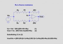
I think the debate was about the relation of input impedances for
equal load to the preceding stages. Is it with numbers according
to this picture R1+ZR1=R2 or different as claimed here and there ?
equal load to the preceding stages. Is it with numbers according
to this picture R1+ZR1=R2 or different as claimed here and there ?
Sorry but you forget to include the source resistance Rsource.
With Rsource=0, cmrr is always perfect, no matter what resistances are used as long as they have the same ratio on both sides.
It is Rsource that changes this all.
Hans
Correct but with unequal value resistors the 'summing' opamp will have increased CM distortion.
So at the end of the day, assuming zero OP impedance driving the final stage, you are balancing any distortion caused by unequal differential loading
of the 'driver' opamps versus CM distortion of the final opamp.
Unfortunately not many people pay much attention to CM distortion or even understand it. As was pointed out in the OPA1656 thread by TI engineers, a
lot of progress has been made to lower it significantly so using the right chips and you are pretty safe but if you want to wring the absolute best
performance it's worth considering.
TCD
R1 + ZR1 is not al all R2, but R1/ZR1 = R2/ZR2.I think the debate was about the relation of input impedances for
equal load to the preceding stages. Is it with numbers according
to this picture R1+ZR1=R2 or different as claimed here and there ?
The formula shows that equal load for both legs is a no no, because Rs from the preceding stage is load independent and the same for both legs. That ruins the equal load theory.
Hans
Ignoring source impedance for a moment (say it is zero)
of course R1/ZR1 has to be R2/ZR2 for full CMRR, but
people discussed "unequal legs" here and even wrote that
measurements and or simulations confirmed it. So what
about "equal load" on positive and negative side, is it a
thread hoax or not ?
of course R1/ZR1 has to be R2/ZR2 for full CMRR, but
people discussed "unequal legs" here and even wrote that
measurements and or simulations confirmed it. So what
about "equal load" on positive and negative side, is it a
thread hoax or not ?
Could you please eloborate what CM distortion has to do with the subject CMRR that we are discussing ?Correct but with unequal value resistors the 'summing' opamp will have increased CM distortion.
So at the end of the day, assuming zero OP impedance driving the final stage, you are balancing any distortion caused by unequal differential loading
of the 'driver' opamps versus CM distortion of the final opamp.
Unfortunately not many people pay much attention to CM distortion or even understand it. As was pointed out in the OPA1656 thread by TI engineers, a
lot of progress has been made to lower it significantly so using the right chips and you are pretty safe but if you want to wring the absolute best
performance it's worth considering.
TCD
However: In the first sentence you mention that with unequal value resistors CM distortion increases.
But in the second part I understand the opposite because with unequal differential loading (is equal resistor values) CM distortion increases ??
Hans
Ignoring source impedance for a moment (say it is zero)
of course R1/ZR1 has to be R2/ZR2 for full CMRR, but
people discussed "unequal legs" here and even wrote that
measurements and or simulations confirmed it. So what
about "equal load" on positive and negative side, is it a
thread hoax or not ?
Maybe Terry can explain.
Hans
Could you please eloborate what CM distortion has to do with the subject CMRR that we are discussing ?
Just covering *all of the + and - performance attributes of the two circuit
variations.
IME if you want the best sounding circuit, it's worth paying attention to CM distortion, it can make a difference.
However: In the first sentence you mention that with unequal value resistors CM distortion increases.
Yes, correct. Unequal resulting in different impedances presented to each + and - IP's of phase summing opamp. Jan's circuit does this. It also depends
on the opamps sensitivity to these effects. Something like a 553x will be degraded, with some of the newer TI opamps it may be a lot smaller.
But in the second part I understand the opposite because with unequal differential loading (is equal resistor values) CM distortion increases ??
Hans
No, unequal differential loading (to the driver opamps) caused by equal value R's will result in lower CM distortion of the summing opamp.
There may be some distortion artifact from driver opamps as a result of the unequal loading but looking at Samuel Groner's opamp paper, the effects of CM distortion are much more significant.
So both topologies offer similar CMRR but one has potentially lower CM distortion - I'd say use equal value R's and move on.
TCD
Ignoring source impedance for a moment (say it is zero)
of course R1/ZR1 has to be R2/ZR2 for full CMRR, but
people discussed "unequal legs" here and even wrote that
measurements and or simulations confirmed it. So what
about "equal load" on positive and negative side, is it a
thread hoax or not ?
To be clear, Jan was the one who first suggested the equal load advantage.
I don't see any major advantage of presenting equal loads to the driver opamps unless they were super low value R's causing significant distortion.
In this case equal loads will result in equal distortion and as such any even order will more effectively cancel in the summing opamp. But with the R
values presented here load generated distortion would be next to non existent.
Still, it's worth looking in to these circuit variations - it makes you think things through, possibly in a way that you hadn't previously and you just might learn something. 🙂
TCD