What is the idle/peak current you expect M7/M8 to operate in??
ZVN3306 has a stability limitation of 30ma.
In the given schema 30mA equals 30V at the input, that should be enough 🙂 (for an audio input signal). As the 3306 can handle up to 100mA, it will protect the following stage up to 100V (that needs to be capable of delivering 100mA). Static is no problem, I would not know a source (of static electricity) that would deliver 10mA (any way, any source that would deliver more then 100V at more then 100mA would be a Sirius danger for all kinds of things, it would endanger your life, your pre-amplifier's input will be a secondary concern, and it is not the task of this circuit to protect against that).
At the hardware store I found these 'Wolfcraft 3628470 Suction Spring Clamp' (and others, I'm not working for Wolfcraft 🙂) they are really helpful, holding boards while assembling, or cable ends while soldering (and more). If you (all) did not know about these, check them out 🙂
This thread with a lot of interesting informations and facts needs actually a TOC.
Who can make this?
BTW - What means the abbreviation "MPP" ?
Maybe "Master(reference) Phono Preamp ?
Who can make this?
BTW - What means the abbreviation "MPP" ?
Maybe "Master(reference) Phono Preamp ?
Joachim - is the Hafler 9300/9500 schematic incorrect? The input to the VAS should come from the input jfets, not the feedback side.
MPP is for My Privat Phonostage.
It went from " Hölzchen zu Stöckchen " though and got blown up quite a lot.
You can find also line stages and buffers here plus i use it as a kind of Blog when i find something interesting-
Problem is that i opened already so many other threads that i did not want to open even more.
Somebody had done work sometime ago to bring more order into the thread but i did not follow up unfortunately.
I did not look at the Haffler carefull enough so i do not know.
I found the input stage interesting.
I did something similar here.
That Phonostage was called the Hulk because it has green Leds in it.
Later it got known as the Crystal after we had shown it on ETF.
I found the input stage interesting.
I did something similar here.
That Phonostage was called the Hulk because it has green Leds in it.
Later it got known as the Crystal after we had shown it on ETF.
I found this in another place but it looks the same.
I think the schematic works.
My phono had also the input buffers that where coupled over the sources.
This circuit is quite fast because it minimises the effect of input capacitance.
The input is a buffer and the parallel symmetric differential stage that follows works in common gate mode so the signal goes into the sources.
Attachments
Is the circuit conventional or did you do your magic wand ?
Nothing special, just as in the datasheet 🙂
We had some success here with bootstrapping discrete buffers and even made a linestage.
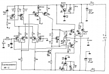
For another project over at the Frickelfest Forum i needed an Opamp buffer.
The goal was using components that everyone has lying around, maybe even since the 70th.
So i chose the NE5532. Conventional buffer and then inverted gain stage with Class A bias plus a discrete Diamond Buffer.
This is a Headphone Amp that drives low impedance but it can also be used as a line stage.
The sound i got in my system was a surprise.
I think i can not make the gain stage any better given the limitations of very low budget but i think i can improve the buffer.
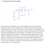
It is AC coupled out of several reasons so bootstrapping the input resistors is possible.
Here is the schematic of the Headamp called The Caveman and the bootstrap idea.
For the resistors i thought 47kOhm is fine.
Then C2 can be 2.2uF for example.
C1 can then be really small.
For another project over at the Frickelfest Forum i needed an Opamp buffer.
The goal was using components that everyone has lying around, maybe even since the 70th.
So i chose the NE5532. Conventional buffer and then inverted gain stage with Class A bias plus a discrete Diamond Buffer.
This is a Headphone Amp that drives low impedance but it can also be used as a line stage.
The sound i got in my system was a surprise.
I think i can not make the gain stage any better given the limitations of very low budget but i think i can improve the buffer.
It is AC coupled out of several reasons so bootstrapping the input resistors is possible.
Here is the schematic of the Headamp called The Caveman and the bootstrap idea.
For the resistors i thought 47kOhm is fine.
Then C2 can be 2.2uF for example.
C1 can then be really small.
Attachments
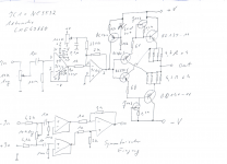
Just for completeness i found this older Electrocompaniet MC Pre-Pre circuit.
Considering the age i find it rather clever.
And I think it's ugly 🙂
There are interesting elements in the circuit so i posted it.
Electrocompaniet made many things different in the old times.
I watch it out of historical reasons.
Electrocompaniet made many things different in the old times.
I watch it out of historical reasons.