For this we could connect the amplification stage and the buffer with wire jumpers, ...
That will work. I will just add jumpers 🙂
You see how the EQ question slows everything down ? That´s the problem. I am ok with jumpers though but please lets not use us any complicated relais business with logic etc.
pls give me a day, tomorrow I have to take care of something else, so I can't go over the values, there's is a few places where we're on the limit with currents and derating. I have to look into that,
I run 2.5 mA through each input transistor 10 mA in total through the first mirror, this give the Jfet CCS a little heat problem as it need's to be set somewhat higher app 50% at 15 ma to let the shunt have some current to work with
Other limit area is the JFET CCS for the buffer....It sees high voltage and is run at 10 mA, so it's also loaded a little high, so the floating mirror CCS may not be susch a bad idea....
I'll not include any other networks than the RIAA, but I do think that Jumpers Will be a good idea
I also think that a double sided layout with a ground-plane would be good (That how they used to do RF layouts at my former job (Sailor VHF-radios)
GND plane can than be split between buffer and frontend.. and jumper connected
Last edited:
For me it would be : 50usec - 70usec that is easy, two different caps
2.2use ( Neumann pole, though this is neither a pole, nor always correct because many lathes roll of 2nd order over 50kHz and not first order, see "Cut and Trust" published in Stereophile ), easy too, just add a resistor in series to the lone 75usec
cap)
Then i have a collection of Decca, EMI, RCA and Mercury classical records. I have also Blue Note, Verve, Vanguard records. Mostly Jazz, some mono. Thats all i ever need.
I have a lot of older Deutsche Grammophon, Telefunken, Philipps etc where some may have the 50usec so this is already covered.
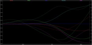
That looks really pretty. Maybe we should apply to the Documenta. That enlarged and put in a frame i would like to put in my living room. Interesting. The biggest variation is in the midrange and treble.
its in the +-3 dB range, but yes most significant in the treble....but not so easy to adjust caps without a switch....but typically those with 70us pole will have treble loss....
Last edited:
Yes, this old recording sound a little dark sometimes. Still, i am not sure if we should go through all this hassle for plus minus 3dB.
Guys you are AWESOME!
I am of no use regarding circuit design with my limited knowledge but if you need help with layout 'possible' debugging/check count me in.
I am of no use regarding circuit design with my limited knowledge but if you need help with layout 'possible' debugging/check count me in.
I also think that a double sided layout with a ground-plane would be good (That how they used to do RF layouts at my former job (Sailor VHF-radios)
GND plane can than be split between buffer and frontend.. and jumper connected
Hi, thats exactly what I will do. plus a few more... :
symmetrical layout
power supply decoupling close to the high current paths
remote sensing for the shunt regulators
input / output separation
thermal considerations
my feeling is that people would want to build standalone phono preamps with this, so the attached layout sketch might make sense - please comment!
Attachments
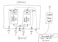
So far that looks right to me. At the input we would also have a second set of RCA jacks for loading and the two wirewound potmeters, one per channel.
remote sensing for the shunt regulators
Not too sure about remote sensing, it may oscillate. Keep the regulator near the preamp and you will fine, at 105mA I do not think that remote sensing will do much good.
my feeling is that people would want to build standalone phono preamps with this, so the attached layout sketch might make sense - please comment!
That is what I would do (did)
Flickr: Search F.d.W.'s photostream
Maybe it is an idea to leave the current source in the power/transformer box, and bring the shunt to the preamp box. Any reactions? let me know.
well, that may lead to parasitic oscillations due to the large parasitic inductance of the cable - something to simulate (try a few microhenry....)
(I know a current source is supposed to behave like an inductor, but there is also parasitic capacitance here....)
(I know a current source is supposed to behave like an inductor, but there is also parasitic capacitance here....)
well, that may lead to parasitic oscillations due to the large parasitic inductance of the cable - something to simulate (try a few microhenry....)
(I know a current source is supposed to behave like an inductor, but there is also parasitic capacitance here....)
You are right, it will be a nice 14MHz transmitter 🙂
could serve as a wireless transmitter to the speakers ;-)
And up to a few KM (it was 20Volts top/top).