the cap is 1u and the input resistor is 1 Meg and the output is 2x2meg in parallel..
Did not see the 1u in the schema, I thought to read another value 🙂 The output resistor could be lower, it goes in a low impedance load (as far as I see). I would take something like 30 to 50 times the load impedance. Anyway I am not sure about the impedance at that point.
Frans I better get in on the buy as well....
PM me, and as soon as I do have the goods (they are ordered and payed) I let you know.
Frans, thanks. I would recommend a small resistor in series with the 100nF snubbers.
Something really small then, like 20 Ohm. I will add that to my drawing here but not post immediately, there may be more comments and if so I will do an updated version in a day or two.
That impedance (2x basis emitter stretch) is setting the currents through the whole amplification stage..
The servo is then shielded from the circuit by the impedance of the current mirror as well...The servo alters the currents through the upper and lover side to balance the DC-offset to uV area.
I have used this servo style before where it's effective and can remove up to 1V source offset in a 28dB application.
No, more like 1 to 2 Ohm. When you use fast diodes it can happen that the snubber resonates.
Ahhh that small, o.k. I draw them in. But to be fair the diodes shown are not mandatory, any fast recovery (non Schottky) will do and most will not need the resistor. Normally I would not buy Schottky's but when selecting rectifier diodes from the LTspice available types, these are the ones to go for.
I use UF4004 without snubber. I would like to use the UF4004 in this circuit because i have a lot of them and they work without trouble. Is it ok that you put the snubbers in plus series resistor just in case we like to experiment ? We can then use them, leave them out or put a resistor in series. It is a small thing anyway but some people report phenomenal differences. I am not one of those.
I use UF4004 without snubber. I would like to use the UF4004 in this circuit because i have a lot of them and they work without trouble. Is it ok that you put the snubbers in plus series resistor just in case we like to experiment ? We can then use them, leave them out or put a resistor in series. It is a small thing anyway but some people report phenomenal differences. I am not one of those.
Yes done so (1.5 Ohm).
Also using a transformer with a 10 Ohm 50 Hz dynamic impedance and 3.300uF shows a 27Amp half cycle current in the diodes, the UF4004 will tolerate 30Amps 🙂
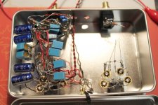
Anyway from the picture I see that you are using a small C-core (or M-core ...) but not a ring-core so you will not see any problems.
I use Block split bobbin transformers. What picture ?
In 3499, but now I have a better look, its a filter there 🙂
If the transformer is less then 40 or 50 VA 24V you will be ok (while using up to 4700uF or there about). After that you need to check it out.
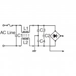
I think a 18VA is more then enough. Yes, that is a common mode choke. I would like to put some before the bridges. Like this .....
As where it should be 🙂 I will draw one in, how many uH are you using? and what value caps?
Last edited:
Right, i also used it behind the bridges between caps with some success but i think this is better.
I made a first sketch of your proposal (input stage only)
Results are not encouraging so far. I used a pair of 2sk389/2sj109 and a quad of sa1360/sc3424, resistive base bias and drain resistors. Output has wandering offset between a few tens of mV, and between the sources I got a constant 200mV over 40R. Poor cart, had there been one....
Next try is with matched small-signal transistors.
Rüdiger
Block transformers are only available with up to 2 x 18V. As an alternative we could use
4 pc with 10VA and 1 x 24V. They are inexpensive and work great. As i said i would like to go double mono. That is the one single thing i found out. Whenever Martina Schöner slept
a phono stage into my house with double mono PSU i could not compete in width of soundstage with a phono stage with stereo PSU although some of my stereo PSU stages sounded better in dynamics, resolution and tonal balance. When i modified them for double mono the world was in order again ( i do not know if this is the right way to express that in english ).
P.S. i also found out that in all experiments we did that i could improve the sound of any phonostage ( then switched to MM ) with a decent pre-pre. The first 20dB of amplification are the most important ones, i concluded.
EI 48 - 16,8 124 - Trafo 10VA, 24V, 416mA - Printtrafos 10-16VA bei reichelt elektronik
This are the common mode chokes i use. They are inexpensive and good. As i already mentioned, some criticized the use of a ferrite ring. See my Nobrainer thread for the alternatives from Panasonic ( Digikey ).
CAF 0,6-100 - Stromkompensierte Drossel, 100mH, 20 - 30mm - Stromkompensierte Drosseln bei reichelt elektronik
CAF 0,6-100 - Stromkompensierte Drossel, 100mH, 20 - 30mm - Stromkompensierte Drosseln bei reichelt elektronik
Rüdiger, i never tried it with Fets but my first MPP with bipolar transimpedance input with the same topology worked just fine.
This are the common mode chokes i use. They are inexpensive and good. As i already mentioned, some criticized the use of a ferrite ring. See my Nobrainer thread for the alternatives from Panasonic ( Digikey ).
CAF 0,6-100 - Stromkompensierte Drossel, 100mH, 20 - 30mm - Stromkompensierte Drosseln bei reichelt elektronik
18Volt is to low, the schema, as given, shows that a 20Vac or higher transformer is needed. The best fit I could find (in the past 15mins) is this one: Digi-Key - TE70045-ND (Manufacturer - 70045K)