This thread is amazing. Especially for me. It changed my life style. A lot. I have luck. My son is a fine french horn and piano player and my wife is a fashion designer and art teacher. They both understand the pain an artist can get through. Still sometimes strange things happen. Today my son talked to me for a while and then he said : Papa, you do not listen to me although you talk back in a way that makes no sense. You are somewhere else. And last week my wife said : When do you go back to regular work. I need winter tires for my car. Anyway, that problem with Balanced In with Fets in transimpedance bugged me so i build a little jig. Deep in my guts i feel there is a solution to null the DC offset and i made some progress but i am just not there. Maybe it comes to me in a dream.
Attachments
And it came to me. We need another input structure. The first MPP i ever published is the key. We just have to substitute the BJTs for Fets, and bingo, it works beautifully. In this circuit the DC offset does not matter as long as it is similar in both the positive and negative input. We can then combine this circuit with the Paradise Lost and have a Fet based transimpedance balanced input. First i was not sure how to call it. One option was
The Marriage of Heaven and Hell but i do not want to have something to do with hell so i named it Paradise Regained, after the second poem of Milton about paradise that never got as popular as his first one Paradise Lost. That may happen to this circuit too because i promised to focus on the Paradise Lost but this maybe is something to throw some Fets in for Rüdiger. I did that for you.
The Marriage of Heaven and Hell but i do not want to have something to do with hell so i named it Paradise Regained, after the second poem of Milton about paradise that never got as popular as his first one Paradise Lost. That may happen to this circuit too because i promised to focus on the Paradise Lost but this maybe is something to throw some Fets in for Rüdiger. I did that for you.
Attachments
Wow!
You're faster than light! That will give me something to chew on over christmas.

Thanks a lot!
Rüdiger
You're faster than light! That will give me something to chew on over christmas.
Thanks a lot!
Rüdiger
I do have the Paradise lost working in simulation....
Will revert with my findings and idea later toady
Will revert with my findings and idea later toady
Hi FdW and Joachim (and all the others who might know),
checked your PS diagram in post 3383, one question: this is something I have seen in quite a few CCS-shunt reg power supplies, that the positive and negative voltage are being regulated with devices of the other polarity (in your case a NPN / p-channel for the positive voltage, a PNP / n-channel for the negative voltage).
Now, these devices have ever so slightly different characteristics especially speed but also parasitic capacitance. did you ever observe an increase in third harmonic due to that, as compared to a situation where you use identical shunt regulator "cells" with the same devices for positive and negative? obviously, this would be damped by the PSRR of the circuit.
just curious.....
I once used two identical regs for each polarity (with excetpion of CCS), with the neg-channel turned upside down. It works well, just take care not to confuse yourself...
Rüdiger
Rüdiger
Two positive regs can be floated off a double secondary and rectification. Like Naim NAP-250 amps did or solutions with LM317s etc.
Two positive regs can be floated off a double secondary and rectification. Like Naim NAP-250 amps did or solutions with LM317s etc.
... and the (ground) return point is where the output grounds of the regs meet?
Rüdiger
Hi FdW and Joachim (and all the others who might know),
checked your PS diagram in post 3383, one question: this is something I have seen in quite a few CCS-shunt reg power supplies, that the positive and negative voltage are being regulated with devices of the other polarity (in your case a NPN / p-channel for the positive voltage, a PNP / n-channel for the negative voltage).
Now, these devices have ever so slightly different characteristics especially speed but also parasitic capacitance. did you ever observe an increase in third harmonic due to that, as compared to a situation where you use identical shunt regulator "cells" with the same devices for positive and negative? obviously, this would be damped by the PSRR of the circuit.
just curious.....
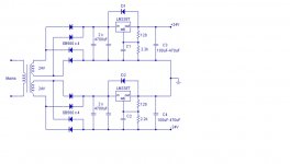
That is easy (to answer). What Onvinyl and Salas said. As you can see (in the design) total (a/mirror)symmetry is already lost, there are two LM317’s used (not one 317 and one 337) due to the fact that the 317 has an way better performance. See 3385.
Also note a small buglet in 3383, the 'adj'-pin is not connected (should be connected to the output).
Regards,
Frans.
Last edited:
Frans, have you build this PSU or does it exist in simulation only ? Anyway, i would like to use your design, so please tell me when you feel confident. I will then build and test it.
Rüdiger, please go ahead. Maybe MiiB found something that is also useful for the balanced transimpedance version so i really look forward to see Michaels result.
Rüdiger, please go ahead. Maybe MiiB found something that is also useful for the balanced transimpedance version so i really look forward to see Michaels result.
Frans, have you build this PSU or does it exist in simulation only ? Anyway, i would like to use your design, so please tell me when you feel confident. I will then build and test it.
Rüdiger, please go ahead. Maybe MiiB found something that is also useful for the balanced transimpedance version so i really look forward to see Michaels result.
This thing will work 🙂 and no, as said before, I did not build it. It is part of my SSA IGBT version, and that one will be built before the end of the year (all parts are sitting on my desk).
Anyway the current source is fine, the real idea that I had was adding the zener to keep the voltage over the regulator constant, this has been simulated, and then again simulated. It works.
The voltage regulator is very much alike the Salas shunt regulator, I did simplify it a bit, and added the 1u to enhance speed (in combination with the base resistor). I do not expect/imagine problems there.
Regards,
Frans.
P.s. Yes I feel confident !
Last edited:
Rüdiger, the drain resistors can be substituted with constant current sources and the bias string of the folded cascodes needs some attention, you are the specialist there.
thanks everybody for chiming in. I know it can be done, in fact, I did build the shunt reg with BD140 as drawn by Joachim, 4x identical (2 for the positive rail, 2 for the negative rail), and then 4 current sources with MOSFETs as per Salas' V1.2 regulator, see attached, again 2x with p-channel, 2x with n-channel. It works fine.
My question was - with the unequal dynamic response on the positive and negative rail, especially with large swing and low-impedance load, do you see an increase in 3rd harmonic due to this?
My question was - with the unequal dynamic response on the positive and negative rail, especially with large swing and low-impedance load, do you see an increase in 3rd harmonic due to this?
Attachments
Yes, Joachim, a lot can be done there. A good PSU is mandatory for this circuit.
I will build a quick sketch tonight to see how stable this turns out to be in its pure form.
Rüdiger
I will build a quick sketch tonight to see how stable this turns out to be in its pure form.
Rüdiger
See an example of arrangement with chips.
Hi Salas,
that may potentially lead to different noise levels on the two rails, as in one channel the noise that is capacitively coupled through the transformer is low-impedance to ground, but not in the other rail. did you build this, was there any noise impact?
thanks everybody for chiming in. I know it can be done, in fact, I did build the shunt reg with BD140 as drawn by Joachim, 4x identical (2 for the positive rail, 2 for the negative rail), and then 4 current sources with MOSFETs as per Salas' V1.2 regulator, see attached, again 2x with p-channel, 2x with n-channel. It works fine.
My question was - with the unequal dynamic response on the positive and negative rail, especially with large swing and low-impedance load, do you see an increase in 3rd harmonic due to this?
Not that I never found, heard or measured.
Differences due to using complementary power supplies, as opposed to equal, are(must be) very small. Given it is a good power supply to begin with.
But then again, once I was a 'shunt-skeptic' and now I am using them 🙂
Last edited:
Hi Salas,
that may potentially lead to different noise levels on the two rails, as in one channel the noise that is capacitively coupled through the transformer is low-impedance to ground, but not in the other rail. did you build this, was there any noise impact?
I had done such things with chips in older times and I don't remember any problems. Naim has been doing it in its amps for 40 years. Cruz had a same arrangement with shunts recently on his veroboard dcb1, said nothing about noise I think. But in high gain & weak input signal low PSRR circuits I don't know. For such circuits there must be measuring of what can intrude in a finished build, and very low noise voltage references in the regs themselves. We can reverse wires on one secondary if the trafos are feeding something parasitic, can't we?
That is true. But then you might end up with magnetic noise (in power amps, most likely) due to the fact that now both current peaks in the input rectifiers happen at the same time. anyway, guess this is splitting hairs.... key is a good regulator and good PSRR if possible....