Do not worry too much Rüdiger. It´s all my fault. I did simply not find the time to look more deep into this because i was too busy. I am sure your solution works fine. You got it working in your circuit in the first place. I ship you the modules next week. If you get them working i know somebody that will be happy. Plus me of cause.
Yes, that is also what i would try. The LM317 is also no good over 10kHz. One could also cascode the LM317 with another LM317 ( aka Walt Jung ) for a big improvement but then we drop over 6V. Has anybody the patients to modify the JHW ( Joachim, Holger, Werner ) that way? I think you, Hesener have done that already so may i ask for a contribution ?
Rüdiger, i check that out.
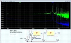
Finding the question (I could read it like that 🙂) of someone looking into cascaded usage of the LM317 (as Jung) I thought to give it a go. The schema and FFT (as attached) gives the result of my try (research).
The cascade version shows a 75dB improvement over the non-cascoded usage.
For this test I use a 15Vac transformer * sqrt(2) for a nominal voltage of 21Vdc. Added to the supply voltage is an noise signal of 4Vpp sinus. The load is a voltage source with an Rser of 1Ohm.
The voltage across the LM317 (including one Vbe and the current set resistor (12.5Ohm for 100mAmp)) is kept constant by using a zener diode, the circuit functions with a minimum value, for the zener, of 5.6Volt. The sample shows a 6.2Volt zener for some headroom.
Let me know what you think of it, and if improvements should be made, but keep it simple.
Anyway, I hope this input was useful.
Happy lurker,
Frans de Wit.
Attachments

Last edited:
That is a huge improvement and it is simple. Good work as far as i can tell. We need of cause a negative version too and the output voltage should be around plus-minus 24V when we take MiiB´s suggestion. The INA217 can take only plus-minus 18V so we need a little local drop for it.
That is a huge improvement and it is simple. Good work as far as i can tell. We need of cause a negative version too and the output voltage should be around plus-minus 24V when we take MiiB´s suggestion. The INA217 can take only plus-minus 18V so we need a little local drop for it.
Here it is +/- 24Volt. Currently I am building my SSA IGBT version, and that is going to use a +- 15Volt version of this power supply for the input stage. But it is not build at this moment, so it is a proposal only (to be continued).
As Jung noted, no need for the LM337, the LM317 will do and has a better performance.
P.s. my build will take place during the upcoming seasons holidays. All stuff is sitting here on my desk, and the cabinet is being machined (will be delivered next week).
Regards,
Frans.
Attachments

I want to throw my last jfets on something decent.
This time, I want current input and balanced operation (with option for unbalanced at the output).
Was there a balanced starless or the like in this thread?
Rüdiger
This time, I want current input and balanced operation (with option for unbalanced at the output).
Was there a balanced starless or the like in this thread?
Rüdiger
Thanks Frans. I would like to use your PSU for the Paradise Lost if you do not mind.
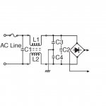
I like it a lot. I assume that the transformer should be plus-minus 18V. I would then add the common mode coils before the bridge like in the little schematic i post. Does your circuit need only a 10uF cap at the output ? That would be really fine. There are small Wima foils with 10uF or does that have too low ESR ?
I will build it and try it out.
Attachments
Rüdiger, the Starless can be modified for balanced when you use the output stage of the Paradise Lost. Should i draw up something that could work ?
Thanks Frans. I would like to use your PSU for the Paradise Lost if you do not mind.
I like it a lot. I assume that the transformer should be plus-minus 18V. I would then add the common mode coils before the bridge like in the little schematic i post. Does your circuit need only a 10uF cap at the output ? That would be really fine. There are small Wima foils with 10uF or does that have too low ESR ?
I will build it and try it out.
The simulator gives (nearly) equal numbers with or without the 10u, so I guess it is not needed at all. Initially I added the 10u to see if adding a capacitive load would destabilize it (it does not). I think I will add a 1u poly in my version (I do have a lot of those).
P.s. I feel honored 🙂
P.s. Yes the transformer should be 18Volts (the simulated transformer uses sqrt(2) for ac/dc conversion so there is some headroom)
Last edited:
The simulator gives (nearly) equal numbers with or without the 10u, so I guess it is not needed at all. Initially I added the 10u to see if adding a capacitive load would destabilize it (it does not). I think I will add a 1u poly in my version (I do have a lot of those).
P.s. I feel honored 🙂
P.s. Yes the transformer should be 18Volts (the simulated transformer uses sqrt(2) for ac/dc conversion so there is some headroom)
Just did a quick check, the original simulation uses a 24Volt transformer and a sqrt(2) ac/dc conversion (that is what I like to use). Recalculating for a 18Volt transformer and a sqrt(3) ac/dc conversion gives a raw voltage of about 30Volts. The LM317 needs 2Volts, Rset 1.25Volts and the transistor Veb 0.7Volts giving about 4Volts, then add some headroom gives a zener of about 6Volts add another 4Volts for Vce and you need 15Volt + 10Volt is 25Volts of DC from the capacitor bank.
So, yes an 18Volt transformer would do (given sqrt(3) ac/dc conversion) if the transformer and capacitor bank is a bit over dimensioned. Anyway I normally would use and (loaded) ac/dc conversion of sqrt(2), and then you will need a 22/24Volt transformer. I hope that clears thing up 🙂
P.s. When using an 18Volt transformer then you need to change R5/6/13/14 to around 820Ohm (for 2mA about)
Last edited:
Thanks Frans, Your circuit is what i was dreaming about : simple and very good. Honestly, i am not a good PSU designer so this help is much appreciated.
Rüdiger, a transconductance balanced Paradise Lost with J-Fets is easy. You can parallel more for less noise if you wish. The transimpedance gives me a bit of headache. I think AC coupling is no problem. Does anyone have a better idea ?
Rüdiger, a transconductance balanced Paradise Lost with J-Fets is easy. You can parallel more for less noise if you wish. The transimpedance gives me a bit of headache. I think AC coupling is no problem. Does anyone have a better idea ?
Attachments
Rüdiger, this is a rough skcetch. Values may change. I trust on MiiB to find the right conditions.
Ricardo, i do not know if i invented that stage but i have not seen that before. Q1, Q2, Q15
can not be without Q9, Q16, Q10 because that establishes zero volt DC at the cartridge when Idss are matched. You can see the same principle in the simple EUVL I/U converter.
I casoded the input Fets with floating Fets of higher Ugs for better performance. The mirrors allow DC coupling into the RIAA but need a conventional plus-minus supply. EUVLs arrangement allows a floating supply with some advantages but needs a big elcaps to couple out. The mirrors output impedance supplies current into the RIAA that then shapes the frequency response by shunting more and more current to ground when frequency goes up. That also has the curious effect that distortion goes lower when frequency go up. This is the opposite of NFB around and OPamp and may be the single most important reason a circuit like this sounds different. The output is a Salas DC B1 buffer that has a cap in front. 10nF give a slight subsonic filter under 25Hz. You can experiment with bigger caps. I think Sampler´s new version has a 49nF. That depends how good your turntable is down there. If you have a miss match of compliance and arm mass or some rumble the subsonic filter may sound better. There is no resistor at the input because the cartridge load alone does the job. You could put a 100Ohm from input to ground to avoid switch on transients when you switch the cartridge with the stgae under juice.
Well, actually the RIIA made active with an Opamp assures at least that the distortion does not rise much in treble but it definitely does not go down with frequency.
Last edited:
Thank you so much for the lightspeed answer.
I see I was not completely wrong in my assumptions and you made it pefectly clear now.
I must digest this and try to understand the connections between the cart and Q1 Q2 and Q15... after that it will be a blast 🙂
I see I was not completely wrong in my assumptions and you made it pefectly clear now.
I must digest this and try to understand the connections between the cart and Q1 Q2 and Q15... after that it will be a blast 🙂
Ricardo, you understood it pretty well. The cartridge simple modulates the source of the Fet against ground.
That is very similar then a BJT common base stage. This is a common gate stage instead that allows DC coupling.
That is very similar then a BJT common base stage. This is a common gate stage instead that allows DC coupling.
Internet is a marvel and life is good.
I must rest now because tomorrow I will take my kid to school early in the morning 🙂
I must rest now because tomorrow I will take my kid to school early in the morning 🙂