How does it compare to Paradise?
The paradise I have built sounds good also (in an outstanding way) but it lacks the ultimate low level detail resolution I get with a much simpler design using fets.
The paradise I have built sounds good also (in an outstanding way) but it lacks the ultimate low level detail resolution I get with a much simpler design using fets.
I am surprised, my Paradise phono has much better low level details compared to my Pass XOno clone , a design similar but better than Pearl Two.
The Xono should sound very different from the Pearl and the Paradise.
The Paradise is exceptional..... but I found more detail in my fet build.
The Paradise is exceptional..... but I found more detail in my fet build.
Last edited:
I heard many versions of the Paradise. From an extremely fatt and tuby sounding version with a Tube PSU to more brighter specimen.
I can say one thing : there is no superiour topology. It is all in the details and execusion ones the design is " transparent ". I mean : Low Noise, Low enough distortion, flat RIAA; low crosstalk, etc.
That makes it so difficult to recommend a particular design.
I can say one thing : there is no superiour topology. It is all in the details and execusion ones the design is " transparent ". I mean : Low Noise, Low enough distortion, flat RIAA; low crosstalk, etc.
That makes it so difficult to recommend a particular design.
The top bargainer Douglas Self sais it in his new book " Electronics for Vinyl ":
. description of six practical projects which range from the simple to the highly sophisticated, but all give exceptional performance
say no more
. description of six practical projects which range from the simple to the highly sophisticated, but all give exceptional performance
say no more
The Xono should sound very different from the Pearl and the Paradise.
The Paradise is exceptional..... but I found more detail in my fet build.
i built a pearl2 but when the paradise was working, i was not going back 😀
Hello together,
I'am planning to build my own paradise phono-pre amp, maybe you can give me some advice on the best way to approach this project. It has been a while since I built my last diy-hifi project (So far, 2x Symasym, LSQR-preamp, some modified china-ebay DAC &some headphone amps).
1. Where can I get the required PCBs?
2. Is this the latest BOM available: google docs?
Regards,
Christian
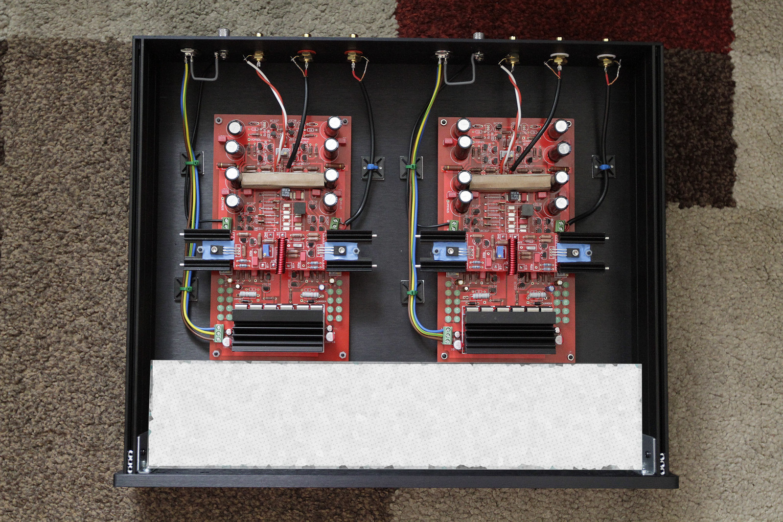
Help sought - My Paradise shunt regs are using 40mA more on the positive rail than on the negative rail. I bought a completed Paradise phono minus prereg as a stop gap until I could build my own.
So with +/- 26V I see 145mA on negative rail and 185 mA on positive. The Calvin buffer is disconnected. I can adjust for 18V on both outputs. Pics of one board here
Michael Lakeman | Flickr The amp works and sounds good to me. Maybe it could sound better though.
So with +/- 26V I see 145mA on negative rail and 185 mA on positive. The Calvin buffer is disconnected. I can adjust for 18V on both outputs. Pics of one board here
Michael Lakeman | Flickr The amp works and sounds good to me. Maybe it could sound better though.
Check the 10 Ohm resistors (R104, R204) for their values. While not ideal, this difference is not alarming. Is it the same behaviour on both channels? And, do you have a scope where you can check if one of the regulators is oscillating?
If that doesnt work , the regulator schematic has typical voltage levels noted, you may want to check those.
By the way, there is a paradise builders thread here: Paradise Builders
where you may want to ask those questions, maybe better than in this MPP thread....
If that doesnt work , the regulator schematic has typical voltage levels noted, you may want to check those.
By the way, there is a paradise builders thread here: Paradise Builders
where you may want to ask those questions, maybe better than in this MPP thread....
Thanks Hesener. Sorry I posted in wrong thread. It's same both channels. Will check resistors and for oscillation.
Michael
Michael
I can say one thing : there is no superiour topology. It is all in the details and execusion.
And that comes from a man who has build any thinkable topo, at least quite a lot! If you think about it, it would be very strange if there were such thing as a single best topology.
I like the Pearl phono.... very good design.... maybe it could be improved with a good psu.
I am sure the psu is an integral part of any amp because it sings along with it.
I use a pair of jfets in the input of my phonostage... and it is quiet. 🙂
Hi RC,
Which circuit are you using? I often experienced (well, three different topos or so...), that a single fet sounds better than paralleld fets if it werent for the noise penalty.
Rüdiger
So the most simple circuit that does the job is the best. Theoretical. Occam´s Razor.
Anyway, with vinyl it is also about taste in sound so reaching the goal in a particular system is not that easy any more. Is is about beautiness in sound ? Then it get´s real difficult. So what is the job ?
Anyway, with vinyl it is also about taste in sound so reaching the goal in a particular system is not that easy any more. Is is about beautiness in sound ? Then it get´s real difficult. So what is the job ?
Hello Joachim
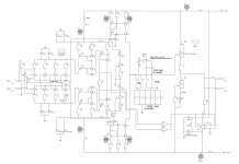
Still trying to understand the paradise schematic and need your input.
There are two voltage references that provide VCASCH and VCASCL.
The are made with a ccs and a zener in each case.
R11 Q97 D2 and R10 Q98 D1
What is the purpose of such a circuit ? In my simulations the circuit works perfectly without these subcircuits......
BTW.... Good sound in the MOC this year.... love your speakers
Ricardo
Attachments
Hi,
I guess D1 and D2 are just used to drop voltage so that the JFETs don't suffer from high Vds and heat losses.
jauu
Calvin
I guess D1 and D2 are just used to drop voltage so that the JFETs don't suffer from high Vds and heat losses.
jauu
Calvin

