They do nothing. They are a hangover from a previous incarnation of the circuit and they were just never removed from the schematic as the circuit was improved. (I think one of the team secretly had shares in 2sk170s ;-)
I see these are not populated in your board.... did you need to adjust other components ? Is there a new schematic ?
Hi,
I guess D1 and D2 are just used to drop voltage so that the JFETs don't suffer from high Vds and heat losses.
jauu
Calvin
Hi Calvin.... But what was the initial purpose of these jfets ?
PS: I saw your phonos in the MOC
"Paradise" and similar attempts to build phono amps.
In the end, after many years, somebody should probably put together all the essential
information necessary to build one of the different incarnations of "this" phono stage in
order to prevent people from reading hundreds or thousands of related forum posts in
various threads over and over again - preferably in a SINGLE post.
I have read a bucnh of stuff in this topic, mostly sent to me by others. I never even knew it was about a phono preamp till just now.
I have read a bucnh of stuff in this topic, mostly sent to me by others. I never even knew it was about a phono preamp till just now.
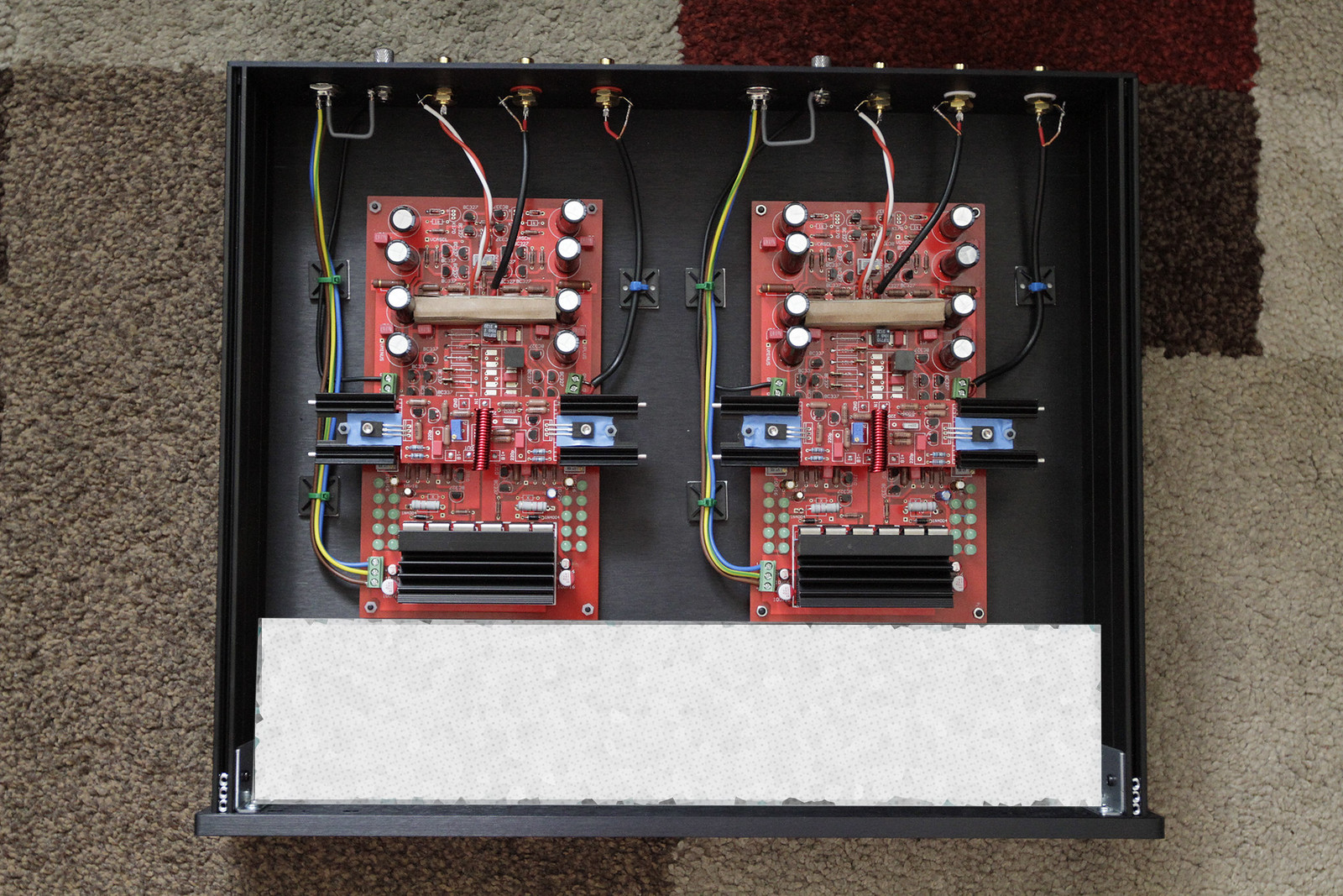
You can see one of these in the picture above. "Paradise" Phono stage, "FPS" phono as seen in "Linear Audio",
"Opus Magnum" (schematic not revealed), "Zion" ready made not yet ready come to mind.
Hi Calvin.... But what was the initial purpose of these jfets ?
PS: I saw your phonos in the MOC
Attachments
-
Post#0002; MPP Basic Structure 1.0.TSC - TINA.pdf79.7 KB · Views: 112
-
Post#0040; Sans Pareil Basic Structure.TSC - TINA.pdf105.8 KB · Views: 114
-
Post#0035; Sofisticated Buffers.TSC - TINA.pdf69.6 KB · Views: 102
-
Post#0035; Jung Buffer.TSC - TINA.pdf44.3 KB · Views: 134
-
Post#0030; Simple Buffers.TSC - TINA.pdf58.9 KB · Views: 112
-
Post#0029; Fet Gainstage with Buffer.TSC - TINA.pdf71.8 KB · Views: 107
-
Post#0028; Fet Gainstage cor.TSC - TINA.pdf47.3 KB · Views: 109
-
Post#0028; Bipolar Gainstage.TSC - TINA.pdf51.2 KB · Views: 112
-
Post#0004; Current Mirrors.TSC - TINA.pdf43.2 KB · Views: 106
-
Post#0003; MPP Basic Structure 2.0.TSC - TINA.pdf87.1 KB · Views: 104
...More
Attachments
-
Post#0137; MPP2 1.0 Structure with values.TSC - TINA.pdf92.2 KB · Views: 85
-
Post#0137; MPP2 1.0 Structure with output servo.TSC - TINA.pdf92.6 KB · Views: 105
-
Post#0114; Source Follower MC.TSC - TINA.pdf38.9 KB · Views: 116
-
Post#0075; ASAP - FET - LNLD.TSC - TINA.pdf54.7 KB · Views: 95
-
Post#0062; ASAP Basic Structure single ended 1.0.TSC - TINA.pdf52.6 KB · Views: 110
-
Post#0062; ASAP - FET.TSC - TINA.pdf48.5 KB · Views: 101
-
Post#0046; MPP Linearit_t dbv.pdf51 KB · Views: 102
-
Post#0046; MPP FFT.pdf54.3 KB · Views: 87
-
Post#0042; MPP Basic Structure single ended Malkolm Hawksford Homag.pdf57.9 KB · Views: 91
-
Post#0041; MPP Basic Structure single ended 1.0.TSC - TINA.pdf56.2 KB · Views: 95
...more
Attachments
-
Post#0238; MPP Fet Headamp SW.TSC - TINA.pdf46.9 KB · Views: 104
-
Post#0201; MPP Fet Headamp Current Mirror.TSC - TINA.pdf45.9 KB · Views: 97
-
Post#0187; Werner OP amp stage.TSC - TINA.pdf30.8 KB · Views: 100
-
Post#0187; MPP Transimpedance Headamp adjustable gain and offset.TS.pdf42.3 KB · Views: 115
-
Post#0187; MPP Fet Headamp adjustabe gain and offset.TSC - TINA.pdf40.5 KB · Views: 109
-
Post#0183; MPP SE RIAA another return from the abbys.TSC - TINA.pdf70.7 KB · Views: 97
-
Post#0170; MPP Single Ended Headamp.TSC - TINA.pdf43.8 KB · Views: 103
-
Post#0155; MPP2 1.0 Structure with +6dB overload.TSC - TINA.pdf92.2 KB · Views: 87
-
Post#0147; MPP Ultimate Basic Structure.TSC - TINA.pdf88.1 KB · Views: 102
-
Post#0239; Phonostage 50Hz breakpoint with coil.TSC - TINA.pdf36.9 KB · Views: 98
O.k. I have 50 more (up to post#1423).
The JFets (Q97 and Q98), resistors (R10 and R11) and Zeners (D1 and D2) can be removed (please correct me if I am wrong 🙂), the current in the mirrors is about 35mA the current in the zenered-current-sources is about 400uA and of no consequence to the loaded resistors (R27 and R29). As you can see (in the PDF-story posted above) it is an artefact of the earliest versions drawn by JG.
The JFets (Q97 and Q98), resistors (R10 and R11) and Zeners (D1 and D2) can be removed (please correct me if I am wrong 🙂), the current in the mirrors is about 35mA the current in the zenered-current-sources is about 400uA and of no consequence to the loaded resistors (R27 and R29). As you can see (in the PDF-story posted above) it is an artefact of the earliest versions drawn by JG.
Last edited:
Just one more question.... I would like to build the paradise with two inputs, one for MC and another one for MM.
In the MM case can I use an inverted SUT ?
I will call it a SDT as it will step down the output of the MM cart ... I plan to use a 10X tx so gain will be reduced 20dB.
As there is a 10x ratio if I load the cart in the secondary with 470ohm, the cart will see 10sqr x 470 = 47k if I am not wrong.... do you believe it can be done ?
3 of the the BJT input pairs could be switched off. Then you get less gain.
If that is still too much you can reduce the idle current in the input.
Problem is that this switching could create a loud plop.
An inverted SUT is a strange idea that comes with some cost but it could work. Have not seen it before though.
Another way to reduce the gain is scaling the RIAA parts. It is approximately proportional to the resistors and anti proportional to the capacitors. When you half the values of the resistors and double the value of the capacitors for example.
In a privat conversation Ricardo asked me if it is possible to get other EQ curves then RIAA to reproduce recordings that where manufactured before the RIAA standart in 1957.
Yes, that is possible by adjusting the components in what is now the RIAA part.
Decca, Deutsche Grammophon, EMI, RCA and others had their own curves before the RIAA standart was agreed on. Also not all of the labels switched immediately to RIAA.
Yes, that is possible by adjusting the components in what is now the RIAA part.
Decca, Deutsche Grammophon, EMI, RCA and others had their own curves before the RIAA standart was agreed on. Also not all of the labels switched immediately to RIAA.
Actually it is not enough to switch off 3 of the input pairs. You have to reduce the idle current too.
Actually it is not enough to switch off 3 of the input pairs. You have to reduce the idle current too.
Thank you Joachim
I believe it might be simpler if I try an inverted SUT
Interestingly Michael Fremer is not very sure about EQ curves......
Phono Equalization B.S. Continues! | Analog Planet
VdH told me that he uses only RIAA EQ because it is the only one capable of replicating frequency AND phase response.
Hans Ole Vitus uses only RIAA curve on his Masterpiece phono and he insisted the others are not real curves but simply tone controls....
He said that NO STEREO recordings where cut with other then RIAA. That can well be but I do not know for sure.
This guides us into the several curves: http://www.pspatialaudio.com/Pspatial_EQ_Guide.pdf
This enables us to calc the Filter values:
http://www.kabusa.com/riaa.htm
This enables us to calc the Filter values:
http://www.kabusa.com/riaa.htm