I agree....will post it tomorrow...then we have a chance to sleep on it
Joachim will you do a perfbofeard..or is it tooo complex for that..??
According to the nice sweedish work i belive theres are more options to tha zener...maybe 3 of theese could do a good figure if run at 5 mA
BCX55/C3V9 (0.5W 3.9V):
#1 @ 1mA: 1.7 1.8 1.7 1.6 1.6 uV
#1 @ 5mA: 1.1 1.1 1.1 1.2 1.1 uV
#1 @ 20mA: 0.94 9.76 0.84 0.79 0.77 uV
#2@1mA: 1.6 1.6 1.6 1.5 1.6 uV
#2@5mA: 1.2 1.1 1.1 1.1 1.1 uV
#2 @ 20mA: 0.97 0.78 0.86 0.76 0.77 uV
Last edited:
I can build that, no problem. The PCB can be designed parallel . When i find problems i can report.

I can build that, no problem. The PCB can be designed parallel . When i find problems i can report.
cool - this is progressing really fast. have time monday night to start working....
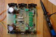
This is where I'am Now..Freeze...
Think that PCB and Perfboard can comence...🙂
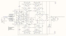
Wrong designation on two helper transistors, all should be BC327-337
By the way, that buffer looks awesome...don't know what to call it.. driven diamond cascode..??
michael
Think that PCB and Perfboard can comence...🙂
Wrong designation on two helper transistors, all should be BC327-337
By the way, that buffer looks awesome...don't know what to call it.. driven diamond cascode..??
michael
Attachments
Last edited:
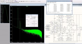
hmmm that is what happens when you simulate deep in the circuit, you have to set the caps high, or completely remove them, Will set them back to right value later today....but where it say 1 its supposed to be 10mF
There is still a small improvement to be made. R17/R29 can be split in two (2 x 220) and from the center a capacitor could be connected to ground (470/1000uF). I know the power supply is very good, and this is not ‘needed’, but still…
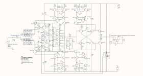
Will add that...and post new schematic later toady.... to be clear I suppose you mean R27 and R 29.. True that takes even more noise out, and reduces the resistor current noise at the same time.. good thinking..! (again)
The C-3-4-8-9 is supposed to be 10mF and 3.3 Uf for decoupling, though the decoupling is not needed on a high impedance current mirror, I can still hear it, and if at Mundorf tinfoil cap is used it add's a pleasant calm warmth to the sound. ( just one of those things you can hear, but not explain)
The C-3-4-8-9 is supposed to be 10mF and 3.3 Uf for decoupling, though the decoupling is not needed on a high impedance current mirror, I can still hear it, and if at Mundorf tinfoil cap is used it add's a pleasant calm warmth to the sound. ( just one of those things you can hear, but not explain)
Last edited: