with the PM-BF 4391 the gain drops app 3 dB...could be possible to increase gain by running uneven resistors in the two strings...eg by lowering the backside to 220 ohm the gain increases by 3-4 dB...
If this different current approach is used for more current and gain it could be useful to change mirror transistors to some types like the KSA3503/KSC1381 as the bottom pair sees some 200 mW dissipation
If this different current approach is used for more current and gain it could be useful to change mirror transistors to some types like the KSA3503/KSC1381 as the bottom pair sees some 200 mW dissipation
I tried that transistors in a much more complicated Gilbert 2I mirror and they did not work. I never found out why. They have much lower Hfe then BC550C, 560C so at first glance i would assume less output resistance from the mirror. About what backside are you talking about ? I am quite surprised how much attention this little circuit draws. When we put our knowledge together this can turn into something nice and simple i think.
the backside where the current is tapped for the RIAA...if you unbalance the mirror with lower resistors there you increase current and thus the gain... if we increase there we also increase dissipation.. so a pair of TO126 with high HFe may be the right medicine...
Last edited:
Honestly i do not know better then KSA3503/KSC1381 or the Sanyo equivalent. With luck we get Hfe of 200. Interesting idea to unbalance the mirror. That did not come to my mind before.
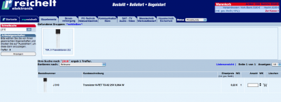
I think i found a transistor that should work. It is a medium power SMD part with Hfe of 500. Big enough to solder by hand :
http://www.diodes.com/datasheets/ZXT690BK.pdf
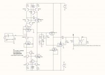
Here the circuit you suggested or is there a mistake ?
http://www.diodes.com/datasheets/ZXT690BK.pdf
Here the circuit you suggested or is there a mistake ?
Attachments
No it's not up and down unbalanced, but left reight so the current is kept low through the input and then the current is upped to the RIAA node. This increases gain.
I think i found a transistor that should work. It is a medium power SMD part with Hfe of 500. Big enough to solder by hand :
http://www.diodes.com/datasheets/ZXT690BK.pdf
Here the circuit you suggested or is there a mistake ?
16pF Cob though?
> I think i found a transistor that should work.
Is there a PN complementary ?
Also hfe not quite flat except at 100mA .....
🙁
Patrick
Is there a PN complementary ?
Also hfe not quite flat except at 100mA .....
🙁
Patrick
The complementary is the ZXT790. Yes, G/BW is "only" 40MHz.
Thanks Michael. Now i understand. Very clever.
I have another trick to raise the power that can be burned in the mirror.
Just double the BC550C/ BC50C in the high current position. It works like a treat. I do like that in the Opus Magnum that also burns a lot of current in the mirror. The compound transistor created has now ( Hfe1 + Hfe2) / 2 and double the power capacity.
The dissipation is not so much that outer as the inner pair....by doubling the transistor the dissipation is only 100 mW on the lover transistors...could be we need some degeneration for current sharing
my RIAA is at bit off as it lifts the lower registers app 1 dB <100 Hz
my RIAA is at bit off as it lifts the lower registers app 1 dB <100 Hz
Attachments
Last edited:
Looks kinky, but a menage-a-trois mirror with identical devices seems more natural.
(the 4391 FET is one of those devices where the aftermarket parts vary quite a bit from the '70s Siliconix original)
(the 4391 FET is one of those devices where the aftermarket parts vary quite a bit from the '70s Siliconix original)
Cool ! Tell me how the two versions sound. I really appreciate your effort.
Excellent Joachim, it's just that cart loading thing comes to play. I chose 200 Ohm for DL, as it gave me closest match tonally to transimpedance input and right gain. Other then that, I'm very pleased with it 🙂
Performance is at the same level between two arrangements. I'm not very good at describing listening experience (don't have stereophile subscription 🙂) but it's really staggering as how something so relatively simple can sound so good. Sophisticated simplicity, as you said, yeah, it always works.
Anyhow, I had some more spare time to play with it and here's where I'm currently at. I rearranged to transconductance input as I was unable to get satisfactionary results with transimpedance and mirrors with helpers running straight to riaa network. Output impedance was really to high, so couple hundreds of pf here and there made huge difference on trable/bass. I made some notes in pdf from real life experiences, that may help someone else.
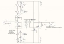
About current mirrors. Helpers are really worth addition, both technically for better riaa matching and sonically, but as with almost all things in life, there is downside. Zeroing output offset was a real nightmare. It can be done, but it is very time consuming as you have to play with almost Mohm resistors for that final couple volts. I was thinking of solution and have some ideas. First thing that can be done, is to place both mirrors on a single heat sink. I sure will do this for the final, as it will improve thermal tracking. Second thing is servoing them. I've attached basic concept that should work, and have minimal if any impact on sound. F corner is right, but I'm not sure there is enough current injection for real circuit. I will try it as time allows.
Today I received couple matched sj74/sk170 pairs for other projects. IF they are matched and IF they are not fakes, I will try them for input and give my impressions.
MiiB: Nice find with that unbalanced mirrors 😉
Attachments
Thanks for all contributing here. Michael and Jacco, the BJT doubling works without problem. I match Hfe anyway so there is no need for degeneration unless you want to use non selected BJTs but then you have the job to adjust so it does not safe time to do it that way. Sampler, i know, the higher the output impedance, the harder to adjust DC.
Servo is the answer when i would put this in production. Both my "strange" servo shown my MiiB and also the bias servo that Sampler shows can work. I tried both versions but i connected the bias servo of samplers topology only to one side. His double sided connection is more convenient because it does not matter if the offset is positive or negative in the beginning.
The mirror with cascode is the exception. Thanks for trying to describe the sound difference. I found too that transimpedance and transconductance can be made to sound good. I think the camps are separated because they compare apples to oranges.
The Starless really allows comparison because the parts are exactly the same.
Look at schematic post 3032 for example. They are Q11, Q5, Q10, Q12. They supply the base current for the mirror transistors. This base current always flows in BJT transistors and is responsible for a lot of effects. In this case ( without the helpers ) it limits the output impedance at the collectors of the mirror. You could look at a transimpedance RIAA as a frequency dependent voltage divider. Consequently you loose gain when the output impedance of the mirror goes down provided the values of the RIAA components are hold constant.
Sampler was in post 3035 able to raise the gain to useful values by using the helpers.
He was complaining about too little gain with my original schematic and by suggesting the helpers to him the problem was solved.
He was complaining about too little gain with my original schematic and by suggesting the helpers to him the problem was solved.