So in the schematic you designed for my benz, I have the helpers that raise output impedance of the mirrors and that is why you reduced R15 from 1M to 500k.
I also see there is no coupling cap between the mirrors and the output buffer.
P2 (10r trimmer) under the CCS of the buffer serves what purpose ?
R2 22k and R1 20r are there for what purposes ?
I also see there is no coupling cap between the mirrors and the output buffer.
P2 (10r trimmer) under the CCS of the buffer serves what purpose ?
R2 22k and R1 20r are there for what purposes ?
Attachments
The 500kOhm has to be split in 2. 1MOhm in the RIAA and 1MOhm before the buffer.
A 10nF ( or a bit more ) has to be put between the RIAA and the buffer. Sorry, i did not draw that detail. DC coupling will not work without servo. The trimmer is there to adjust output DC of the buffer. R2 provides a DC path to avoid a plop when you connect the buffer. R1 isolates the buffer from the load ( cable ). 20 Ohm is a minmum. In parxis it can be as high as 470 Ohm. You have to try what sound best in your system. I would start with 120 Ohm for example. The circuit you show has a lot of gain because driving the gate of the input transistors isolates the cartridge from the transimpedance chain. If the gain turns out too high you could take out the helpers or adjust the RIAA components. For 6dB less gain you have to half the resistor values and double the cap values. That gives you also less distortion.
A 10nF ( or a bit more ) has to be put between the RIAA and the buffer. Sorry, i did not draw that detail. DC coupling will not work without servo. The trimmer is there to adjust output DC of the buffer. R2 provides a DC path to avoid a plop when you connect the buffer. R1 isolates the buffer from the load ( cable ). 20 Ohm is a minmum. In parxis it can be as high as 470 Ohm. You have to try what sound best in your system. I would start with 120 Ohm for example. The circuit you show has a lot of gain because driving the gate of the input transistors isolates the cartridge from the transimpedance chain. If the gain turns out too high you could take out the helpers or adjust the RIAA components. For 6dB less gain you have to half the resistor values and double the cap values. That gives you also less distortion.
Put the circuit under current. Measure the DC at the output over R22. Adjust the trimmer to near 0V offset. Plus - minus 5mV is ok. The buffer is thermally stable so that should be easy.
Now that we are starting to understand transimpedance concepts as use in phono stages we can also look at its use in linear amps. As i published before i am building the Buffalo Bill linestage for LÁrt du Son. It is set up in the following way : Transimpedance voltage gain, volume and balance control, buffer. That way i get the least amount of noise because there is no voltage gain after the volume control. In a conventional arrangement that gain after the volume control also amplifies the noise. The buffer is set up as a modified diamond buffer. For the basic circuit see my contribution on the Cascode Diamond Buffer thread. How i designed the voltage amp will be shown here in some detail.
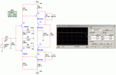
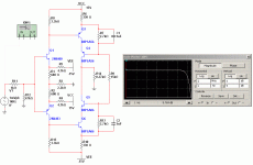
It all started with a topology designed by Prof.Hawksford and Dr.Mills, people i worked intensively with in the 90th at the University of Essex. It is rather basic and can be improved but even this simple circuit is not bad at all in performance. Set up in this way the -3dB point is at 4.7MHz and the gain is ca.6dB. It is stable with little overshot and can reproduce a 100kHz square wave without much deformation. It can swing 5.72V in class A.
It all started with a topology designed by Prof.Hawksford and Dr.Mills, people i worked intensively with in the 90th at the University of Essex. It is rather basic and can be improved but even this simple circuit is not bad at all in performance. Set up in this way the -3dB point is at 4.7MHz and the gain is ca.6dB. It is stable with little overshot and can reproduce a 100kHz square wave without much deformation. It can swing 5.72V in class A.
Attachments
Now that we are starting to understand transimpedance concepts as use in phono stages we can also look at its use in linear amps.
Attachments
Thanks Jack. I have developed that circuit a little further but i am busy the next hours.
I will come back in time.
I will come back in time.
I have now put the circuit as is through the paces and have included it in my signal chain.
It worked right away with the exception that i put a PNP Transistor in one position of the left channel where an NPN should be. I am a bit handicapped with my eyes at the moment because i broke one glass of my spectacles and i am wearing 20 year old glasses now that show me only half what i can see usually. If i would criticize what i hear the circuit errs on the slightly warm side compared to the Buffalo Bill buffer alone. This in the best british tradition. Everything is there but slightly " under the hood ". I think this is an attractive detour from the ice cold and analytical sound i hear often from expensive IC stuffed commercial preamps. I drive this circuit from an unregulated supply that uses simple RC filtering so a better PSU can improve the sound much i think. Even with this primitive PSU the circuit is dead quiet. A good sign. On the other hand the circuit can be improved. First i will add constant current sources to the input pair. That gives better PSU rejection and allows me to trim DC offset at the output. At the moment offset is a bit under 1V negative in both channels without any matching or adjustment. I have an input cap on my power amp so it works in my system but may cause trouble in a fully DC coupled system. Watch this space.
It worked right away with the exception that i put a PNP Transistor in one position of the left channel where an NPN should be. I am a bit handicapped with my eyes at the moment because i broke one glass of my spectacles and i am wearing 20 year old glasses now that show me only half what i can see usually. If i would criticize what i hear the circuit errs on the slightly warm side compared to the Buffalo Bill buffer alone. This in the best british tradition. Everything is there but slightly " under the hood ". I think this is an attractive detour from the ice cold and analytical sound i hear often from expensive IC stuffed commercial preamps. I drive this circuit from an unregulated supply that uses simple RC filtering so a better PSU can improve the sound much i think. Even with this primitive PSU the circuit is dead quiet. A good sign. On the other hand the circuit can be improved. First i will add constant current sources to the input pair. That gives better PSU rejection and allows me to trim DC offset at the output. At the moment offset is a bit under 1V negative in both channels without any matching or adjustment. I have an input cap on my power amp so it works in my system but may cause trouble in a fully DC coupled system. Watch this space.
Do you mean the Buffalo Bill is a buffer... no gain... What is the gain of the power amp that you are using ?
I wonder how CCS might modify your positive first impressions related with this last build.
IMO a good psu with the simplest amp is much better than a complex amp with very good PSRR, powered by an average PSU.
PS:
I too suffer from spectacles disease so I understand perfectly what you mean 🙂
I wonder how CCS might modify your positive first impressions related with this last build.
IMO a good psu with the simplest amp is much better than a complex amp with very good PSRR, powered by an average PSU.
PS:
I too suffer from spectacles disease so I understand perfectly what you mean 🙂
Last edited:
As i said, the Buffalo Bill is a buffer but that has an elaboration of the circuit here as voltage gain before the volume control when needed.
When the eyes get worse the ears get better i hope 🙂
Here is how i developed the circuit further. It has now the CCS`s and the Hawksford cascode is clamped with Leds for more stability. Also shown is a Fet version that represents a considerable simplification if you have P-Channels. C1, C2 values come right out of my head. They have to be adjusted for best time ( squarewave ) response.
What can be improved over this ? Cacoding the input too comes to mind but on the other hand the gain of the input stage is very low so not much can be won at the cost of complication. I think i like it as is.
Attachments
I particularly like the fet version.
PS:
I agree that the ears get much better when you loose a small fraction of your vision. That is why I do not mind anymore... I can hear really good nowadays.
PS:
I agree that the ears get much better when you loose a small fraction of your vision. That is why I do not mind anymore... I can hear really good nowadays.
I can even see very good with the right spectacles but i am so busy before Vienna that i did not find the time to go to the doctor.
I like the Fet version too.
Other Fets could be used with small modification to the resistor values.
I like the Fet version too.
Other Fets could be used with small modification to the resistor values.
The fet version is super clean.... might sound powerfull and spacious with a good PSU.
I believe it is DC coupled right ?
I believe it is DC coupled right ?
Wire
Hi Joachim,
I was just gonna tell you that you may borrow my glasses 😉
Looks GOOD my friend, I like both !
Perhaps I'll give it a try next week on a perf board.
Stop teasing me Joachim 🙂
atb,
Audiofanatic 🙂
Hi Joachim,
I was just gonna tell you that you may borrow my glasses 😉
Looks GOOD my friend, I like both !
Perhaps I'll give it a try next week on a perf board.
Stop teasing me Joachim 🙂
atb,
Audiofanatic 🙂
Yes, try it and give me your impression. It can be setup with conventional global feedback too. It should work with any low level transistors. I used 2SA1015 and 2SC1815. 4 cent a piece at Reichelt.
Looking good and seeing good can be quite different 🙂
Looking good and seeing good can be quite different 🙂