MOX_EQ
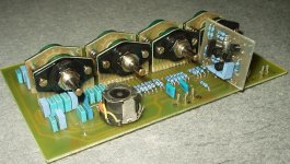
The simplified equalizer uses standard parts, which are easily available. Certain characteristics of the simplified version are slightly worse in comparison with the characteristics of the complex one, but this does not adversely affect performance of the equalizer in an active crossover (for which it has been designed).
The filter has been tested and works satisfactorily.
Attachments
thats exactly what I had in mind but couldn´t realize it.
How easy is it to make a coil like that?
It shouldn´t be so hard, right?
How easy is it to make a coil like that?
It shouldn´t be so hard, right?
Parametric EQ stuff
Hello moamps,
First of all, great looking design on the EQ.
I have some questions.
How can it be a parametric EQ when you clearly have dependencies between Q and fo?
A parametric EQ section is a circuit that lets you change the three defining parameters (fo gain and Q) individually, without any influence on the other two parameters.
\Jens
Re: Parametric EQ stuff
Hi Jens,
from
http://www.rane.com/note101.html
"Constant-Q Graphic Equalizers"
"It should be obvious by now, that parametric equalizers must be based upon totally different topology than are graphic equalizers, since all three parameters are independently adjustable.
Well, some are and some are not.
Some parametrics (I will be kind and not name them) offer adjustment of amplitude, center frequency and bandwidth that are not independent. But since you can adjust each, they get away with it. Those parametrics that offer truly independent adjustment (and there are many) are indeed based on different topology. The heart of these designs is a bandpass section called a state-variable filter."
It's parametric EQ.
Regards
JensRasmussen said:I have some questions.
How can it be a parametric EQ when you clearly have dependencies between Q and fo?
Hi Jens,
from
http://www.rane.com/note101.html
"Constant-Q Graphic Equalizers"
"It should be obvious by now, that parametric equalizers must be based upon totally different topology than are graphic equalizers, since all three parameters are independently adjustable.
Well, some are and some are not.
Some parametrics (I will be kind and not name them) offer adjustment of amplitude, center frequency and bandwidth that are not independent. But since you can adjust each, they get away with it. Those parametrics that offer truly independent adjustment (and there are many) are indeed based on different topology. The heart of these designs is a bandpass section called a state-variable filter."
It's parametric EQ.
Regards
More EQ stuff
Hello,
Without wanting to start a fight on definitions (or any other kind of fight BTW) I find that the term "parametric" means that parameters are independent of each other. Any of the three available controls can be altered without affecting the other two. For example, a change in boost will not effect the Q or center frequency of the filter.
However there is something called Quasi-parametric Equalizers
The quasi-parametric EQ allows control over the Q, center frequency and gain of a filter (just as a true parametric) however these components of the filter may be interactive. For example, changing the center frequency and the gain of a filter will also change its Q.
The advantage of these units are the substantially lower cost than true parametrics. With the exception of infinite-depth notches, the same response curves can be achieved on quasi-parametrics as their more sophisticated counterparts. Of course, these curves will be harder to achieve since all adjustments affect the others.
🙂
\Jens
promitheus said:How easy is it to make a coil like that?
Hi,
isn't so tricky. From say Conrad you can order "shalen-kernsatze" (502105-33 and few parts more) and ca 10m 0.2 dia or so copper wire. And little time, Samstag Nachmittag 😉.
Regards
Well I agree with Jens that a parametric equalizer means you can change any of the 3 parameters without effecting the other 2. It´s all anyway a definition thing.
About the coils, yeah I know those cores but is it a matter of turns only or do you need an LCR meter to be sure?
About the coils, yeah I know those cores but is it a matter of turns only or do you need an LCR meter to be sure?
Re: More EQ stuff
Hi,
"Parametric" means ONLY that you can adjust all 3 parameters; Q, Fo and gain. IMHO.
Not allways. (two antilog pots (or VCA's) and few ICopams can be cheaper than one good inductor). Also, I was compare some "true" parametrics (dbx series 900, etc.) and simple "fake", and for me "fake" sounds better.
Regards
JensRasmussen said:Without wanting to start a fight on definitions (or any other kind of fight BTW) I find that the term "parametric" means that parameters are independent of each other.
Hi,
"Parametric" means ONLY that you can adjust all 3 parameters; Q, Fo and gain. IMHO.
The advantage of these units are the substantially lower cost than true parametrics.
Not allways. (two antilog pots (or VCA's) and few ICopams can be cheaper than one good inductor). Also, I was compare some "true" parametrics (dbx series 900, etc.) and simple "fake", and for me "fake" sounds better.
Regards
promitheus said:About the coils, yeah I know those cores but is it a matter of turns only or do you need an LCR meter to be sure?
Hi,
you need LCR meter or scope and some audio generator or some PC-based audio analyzator.
Regards
Updated schematics and second layout
Hello all,
I updated the schematics and PCB version for the group.
They can be found as PDF's here:
http://www.delta-audio.com/Active filter two.htm
Please comment so we can get this thing running 🙂
\Jens
Hello all,
I updated the schematics and PCB version for the group.
They can be found as PDF's here:
http://www.delta-audio.com/Active filter two.htm
Please comment so we can get this thing running 🙂
\Jens
Nice work Jens. 😀 I've traced through the schematics and they look good. I should have time to trace through the PCB tonight.
Good job, Jens!
I've seen that your layout uses dual in line sockets (single opamp?) instead of moamps' SIL for the discrete opamp.
This gives the opportunity to use standard opamps, but is left unclear if those who still want to use discrete opamps will have to make their own adapters or if you or tiroth are going to make a suitable layout in order to produce such pcbs also while we are at it.
In the wiki there was also a mention to regulators (Jung type): are you planning to make boards for them also or should we go with the group buys currently in progress?
Cheers
Andrea
Stuff
Hi,
The module is made with standard dual op amps and no copy of the Jung regulator is plannede. As for descrete opamps I have no plans for that on this board.
However I'm designing a +- 15V supply to be used with my other filter project.
\Jens
Hi,
The module is made with standard dual op amps and no copy of the Jung regulator is plannede. As for descrete opamps I have no plans for that on this board.
However I'm designing a +- 15V supply to be used with my other filter project.
\Jens
I am not sure but I think there is a problem with the PCB pdfs. I see the bottom and above layer the same.
I think you have the same thing there.
I think you have the same thing there.
PDFs
Hello,
I can't find any porblems with the PDFs - do you have different names for the two layers (Top and Bottom)?
If the problem persists I can mail you the files - just mail me and I'll answer ASAP
\Jens
Hello,
I can't find any porblems with the PDFs - do you have different names for the two layers (Top and Bottom)?
If the problem persists I can mail you the files - just mail me and I'll answer ASAP
\Jens
Andrea,
I wouldn't mind doing a layout for the discrete opamps, but I wonder how much interest there would be in a buy. It is expensive to make lots of small boards.
promitheus ,
Are you sure? There is ground fill on both sides...
I wouldn't mind doing a layout for the discrete opamps, but I wonder how much interest there would be in a buy. It is expensive to make lots of small boards.
promitheus ,
Are you sure? There is ground fill on both sides...
If you see the Wiki there are >150 of these boards "requested" if everyone confirms the interest, but have no clue if they will.
My idea was that it can be nice to have the discrete opamps with PCBs of the same quality of the main PCB, but only if it can be done at a "right" price.
Cheers
Andrea
My idea was that it can be nice to have the discrete opamps with PCBs of the same quality of the main PCB, but only if it can be done at a "right" price.
Cheers
Andrea
Moving on.....
Hello,
All I'd like to know is weather or not to start cleaning up the schematics and the PCB.
\Jens
Hello,
All I'd like to know is weather or not to start cleaning up the schematics and the PCB.
\Jens
- Status
- Not open for further replies.
- Home
- Source & Line
- Analog Line Level
- MOX - active crossover