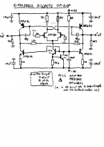
 we've got a problem here
 The solderface even zipped is too big to be attached here

This file cannot be divided into smaller parts

For those interested e-mail me . I'll send you the Cu side *15
best regards
Anael
PS we are also designing a DAC , but WITHOUT oversampling , as seen on the TNT Convertus .
The input is a CS8412 , some 74HCXXX , some nice PCM 1702 and the I/V stage found in the D1 but unbalanced . We are still thinking of how to get rid of the HF junk at 44100 and upwards .
Maybe an opamp like this , with no feedback ? ( In that case 40dB open loop and 20kHz bandwidth.Maybe a very small amount of feedback will do it
"Human ear is a very good low pass filter..."
Like in YBAs integrated CD players 😎
I am still thinking of designing an X version of this opamp , for low gain applications like pre-amps , with something like *1,5 gain .
Later .
While we are here , let's explain what we want to do .
Use the benefits of X feedback , in opamps , so to use them as simple preamps modules or active crossovers .
My goal : designing an entirely balanced active crossover 🙂 with those modules
I have to test it , but I have no doubt it works fine . With the trimpot on the CCS we should be able to achieve direct coupling , both at inputs and outputs .
Feedback welcome
Regards
Anael
Attachments

Andypairo said:I guess that many of us are still waiting for Godot (aka Pass DIY Xover 😉 ), and since this is a daring project there's a little fear to take the wrong route.
If Nelson wasn't planning to release his own project we would probably be involved in a group buy for this x-over (or for Uli's one)....
As this came up in my email again today, I realize that people
aren't aware that I killed the project after I compared MOX
discrete gain stage to page 31 of the XVR1 owner's manual.
www.passlabs.com/pdf/XVR1MAN1.PDF
MOX Boards Wanted
Hi,
Is it possible to buy a set of boards for a stereo 2-way MOX?
I think the group buy has long passed, so if anyone has what I need, please contact me.
Thanks,
Vince
vin.din@verizon.net
Hi,
Is it possible to buy a set of boards for a stereo 2-way MOX?
I think the group buy has long passed, so if anyone has what I need, please contact me.
Thanks,
Vince
vin.din@verizon.net
Vince,
This is not the right thread -- the group buy one is here.
http://www.diyaudio.com/forums/showthread.php?threadid=32095
(I know it is confusing) Email me or just check out my website for details.
This is not the right thread -- the group buy one is here.
http://www.diyaudio.com/forums/showthread.php?threadid=32095
(I know it is confusing) Email me or just check out my website for details.
Hi all,
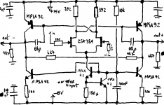
I was wondering, the mox is made of a discrete opamp, but why (for the final version) is a discrete opamp as follower used, and not an open loop follower? Borbely has some simple and good working ones.
I was wondering, the mox is made of a discrete opamp, but why (for the final version) is a discrete opamp as follower used, and not an open loop follower? Borbely has some simple and good working ones.
Bricolo said:I was wondering, the mox is made of a discrete opamp, but why (for the final version) is a discrete opamp as follower used, and not an open loop follower?
Hi,
MOX was built with SK equal component filter type. This means that any discrete amp that's part of the filter should have gain. A discrete amp is used as a follower only at the balanced output stage.
Regards,
Milan
Yes I know that,
But I wondered why the buffer is made of a closed loop opamp, instead of a "true" buffer
But I wondered why the buffer is made of a closed loop opamp, instead of a "true" buffer
I tried to order two mox boards from www.anidian.com a couple weeks ago and I haven't received an email confirmation or anything yet. I have sent several emails and haven't received a response. Is there any other way to get ahold of them?
Looking at the schematic, I see you have 10K volume pots for ea. section of the crossover.
It seems like a perfect setup to use APOX SHM controller here, as one could set permanently offset levels and then adjust all 4 channels simultaneously. By increasing the gain of op amp, one might combine preamp function with high quality active crossover.
From the schematics I've seen so far, this one seems to be the most appealing (especially when it's based on XVR1😉)
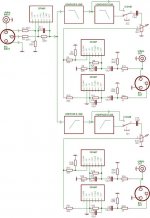
Peter, did you ever try this? I've been trying to understand it, AXOs are new to me. Does the block diagram mean that one builds the HPF and LPF MOX describes (each having opamps) and also opamps for the larger XO? Essentially, what goes in the HPF and LPF blocks of this diagram?
Attachments
There are about 3 or 4 clones of this MOX original.
Some were designed specifically to suit experimentation.
Others were more for a final compact XO.
There are at least 2 PDFs giving full construction and use details. These show the multiplicity of different EQs that can be applied to correct for driver anomalies.
Some were designed specifically to suit experimentation.
Others were more for a final compact XO.
There are at least 2 PDFs giving full construction and use details. These show the multiplicity of different EQs that can be applied to correct for driver anomalies.
I'm pretty much done with my MOX boards. I need to know what value folks used for the C200 and C500 position in the original group buy boards. I've been over the version two and version four info, and can't see a clear answer.
I have a question about the functionality of this type of active crossover.
This question has been haunting me for some time now and I'm pretty sure I asked it somewhere else, but searches don't turn up.
In the FRQ selection sections of the crossover, do these two sections sum when used as a 12db crossover?
In the attached, circled are 25 (x100) in FRQ1 and 25 (x100) in FRQ2.
Do the sections combine to equal 5000Hz? Or, does the settings indicate a 12db, 2500Hz slope?
Thanks,
Vince
Attachments
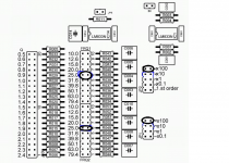
I am not sure what the selections actually select.
As I understand what an active crossover does:
It is two filters. One is High Pass to feed the higher frequency speaker driver via the power amplifier. The other is a Low Pass to feed the lower frequency speaker driver via it's different power amplifier.
A simple version would be a passive single pole RC for the bass/mid and another single pole CR for the treble.
That creates a single pole (6dB/oct) active crossover.
You can use as many poles for steeper slopes as you choose.
eg.
choose a 2pole Butterworth 2.5kHz High Pass and feed that into a second 2pole Butterworth 2.5kHz High Pass. The result is a 4pole 2.5kHz High Pass. But the Q of each HPF multiply to give a net Q of 0.5 (0.7072*0.7072 = 0.5). That is what a 4pole Linkwitz Riley is and called up as LR4
Just as FYI for anyone that might care.
I've driven the FET gain blocks featured in this project into a modular DOA (Discrete Operational Amplifier)
http://www.diyaudio.com/forums/analog-line-level/302174-any-interest-bjt-fet-doas-discrete-op-amps-2520-format.html and here ... https://kadproducts.com/
I've driven the FET gain blocks featured in this project into a modular DOA (Discrete Operational Amplifier)
http://www.diyaudio.com/forums/analog-line-level/302174-any-interest-bjt-fet-doas-discrete-op-amps-2520-format.html and here ... https://kadproducts.com/
Carl_Huff,
What happens when you need a dual op-amp?
The op-amps designed for the MOX-II XO were dual op-amps.
Are they stackable somehow? Doesn't look like it.
What about the foot print? Do they drop into DIP-8 sockets?
Shot of the underside would be nice.
Here's my mess...
http://www.diyaudio.com/forums/gallery/showgallery.php?cat=1764
Vince
Last edited:
- Status
- Not open for further replies.
- Home
- Source & Line
- Analog Line Level
- MOX - active crossover