Hi,
a cheap DMM with a 200.0mVac setting will go far.
These are available from $5 upwards.
A secondhand bench meter reading 500.00mVac can be got for <$100.
Try to get at least one meter that has claimed accuracy on it's best scale (2.000Vdc) of <0.1%.
Don't worry about meter lead/input capacitance. If you measure the input voltage and the output voltage and both are low source resistance and the same frequency then the meter's effect on the circuit is identical and when the meter says the voltage is the same then believe it.
My test switched attenuator is made from 12 DPDT switches and 12off 600r T attenuators, does 0dB to -61dB in 0.05dB steps (yes, 1220 steps).
i have drawn a sketch.
Is this the set up you meant to say, correct?
Still i don't understand how my Fluke can't give me STABLE reading at lower frequencies awhile $5 can.
I will try to look for another multimeter eventually.
This is new basically.
Anyways i still have the problem to build an accurate inverse RIAA since i don't have a bridge to precisely match the parts.
My fluke has a capacimeter but at this point i believe it wouldn't offer me a 0.5% of precision 🙂
Attachments
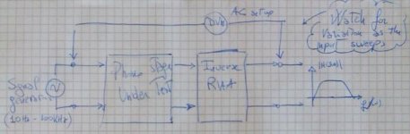
no,
measure the voltage across the input.
Measure the voltage across the output.
Are they the same?
If they are different the comparison method will not work.
You need to add an attenuator to ensure the input and output voltages are the same. Then you can use the comparison method.
measure the voltage across the input.
Measure the voltage across the output.
Are they the same?
If they are different the comparison method will not work.
You need to add an attenuator to ensure the input and output voltages are the same. Then you can use the comparison method.
Stefanoo said:
Conversely if it is not possible to easily and cheaply build the bridge, is it possible to buy the parts with the tolerance required? can anybody sell me the capacitors for the inverse?
Hagerman sells an inverse RIAA network that is accurate to +/-0.25dB here (I use this one):
http://hagtech.com/iriaa.html
At some point you have to decide what is good enough. Denon doesn't show a frequency response flatness on their website for the DL-103, but the Ortofon MC20 MKII (that started me on this thread) has a spec of +/-1dB from 20Hz to 20kHz, so making the RIAA response much better than +/- 0.25dB is a diminishing benefit.
Hi Paul. I am delighted to see your praise for the UPV. It really is a fantastic instrument. I bought mine almost two years ago.
The topic of this thread is also interesting. What I do not understand is the fanatical urge for some people to strive for flatness to the n`t degree. Flatness as such, has little to do with quality. The degree to which the disc-cutters adhered to the RIAA curve is, at best, questionable. Even more disturbing, before entering the cutter head, the signal had, in many cases, travelled through up to eight transformers. But hey, if we just get the chance to bash John Curl on the head, it is worth it. I used to fix Parasound in Norway for about seven years, and I have great respect for the guy. His contribution to the world of reproduced music is impressing.
Regards
Roar
Attachments
paul joyce said:
Hagerman sells an inverse RIAA network that is accurate to +/-0.25dB here (I use this one):
http://hagtech.com/iriaa.html
At some point you have to decide what is good enough. Denon doesn't show a frequency response flatness on their website for the DL-103, but the Ortofon MC20 MKII (that started me on this thread) has a spec of +/-1dB from 20Hz to 20kHz, so making the RIAA response much better than +/- 0.25dB is a diminishing benefit.
Thank you for the link.
I am going to order it.
$29 with free shipping is reasonable.
Roar Malmin said:What I do not understand is the fanatical urge for some people to strive for flatness to the n`t degree.
Although I did myself RIAA +/-0.1dB (caps sorted using a Wavetek LM22A), I fully agree. At the end of the day it's only a nice number:
http://www.diyaudio.com/forums/showthread.php?postid=1680457#post1680457
Roar Malmin said:Hi Paul. I am delighted to see your praise for the UPV. It really is a fantastic instrument. I bought mine almost two years ago.
Roar - very nice - hardly a DIY instrument though! I have been trying to get my company to buy one - we currently use AP Portable 1, ATS2, and Prism Sound Dscope, but the UPV is better than any of these, in particular its 10 ohm output impedance, and adjustable DC level on the signal generator output.
Hi Paul
Try to look at this very versatile mc stepup. It works perfectly for me.
And besides that it has potential for some changes/upgrades.
PS. the transistors can be bought from LC Audio.
Try to look at this very versatile mc stepup. It works perfectly for me.
And besides that it has potential for some changes/upgrades.
PS. the transistors can be bought from LC Audio.
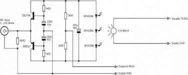
My setup is as follows: the two 2200uf caps has been replaced with two 470uf lyt // two 22uf oscons. The two 2k output resistors have been replaced with two 0,470uf polyprops to avoid any dc on my phono input.
Less input impedance=more gain.
use low resonance lamp and a stable supply like that of a 7812
and it will work perfectly
Less input impedance=more gain.
use low resonance lamp and a stable supply like that of a 7812
and it will work perfectly
pdul said:My setup is as follows: the two 2200uf caps has been replaced with two 470uf lyt // two 22uf oscons. The two 2k output resistors have been replaced with two 0,470uf polyprops to avoid any dc on my phono input.
Less input impedance=more gain.
use low resonance lamp and a stable supply like that of a 7812
and it will work perfectly
This is an adaptation of the Leach circuit. It is certainly elegantly simple. The Rossiter circuit I ended up using has similarities to the Leach circuit, but the addition of the darlington transistors significantly reduces the distortion
syn08 said:
Although I did myself RIAA +/-0.1dB (caps sorted using a Wavetek LM22A), I fully agree. At the end of the day it's only a nice number:
http://www.diyaudio.com/forums/showthread.php?postid=1680457#post1680457
Hi,
great work on the other post.
Just one curiosity:
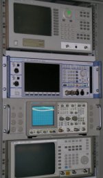
what tools did you use to make all these measurements?
It looks like you have a spectrum analyzer and other good stuff 🙂
How did you measure the 0.1dB RIAA curve? what did you use?
Anyways, great work!
I have 2 questions:
1) as i was researching things on the RIAA i have noticed that an efficient and easy way to check the precision is to use an inverse RIAA at the output and feed the circuit with a square wave.
Check for the quality of the square at the output.
Do you guys think this is a good alternative method?
2) As i was thinking on the point (1) i have thought of taking the RIAA network off of the loop and simply close the feedback on a simple resistive network to evaluate the amplifier itself.
I have noticed that the square wave response of the amp is really poor (i have overshoots at higher frequencies and is just not good)
Is it important to first achieve a good response on the amplifierf and then once this is reached then worry about a precise RIAA network?
Stefanoo said:
Hi,
great work on the other post.
Just one curiosity:
what tools did you use to make all these measurements?
It looks like you have a spectrum analyzer and other good stuff 🙂
How did you measure the 0.1dB RIAA curve? what did you use?
Anyways, great work!
Here, HP3562A (for LF) and HP89410A (for HF). 0.02dB precision with synthesis capability. The graph is the difference between the measured response and the theoretical/synthetized pole-zero RIAA response.
oh my goodness.....good for you!!
It's nice to have all these equipment available.
I wish i would have more.
In the near future i might consider buying a HP sound analyzer.
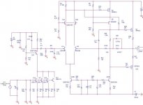
I am making more measurement on the circuit (i will attach the schematic).
For this test i took off the capacitors that are responsable for the RIAA equalization
Probing across R4 shows that when Q3 turns on the input stage starts to be loaded and there is distortion.
Might this be due to the input capacitance of Q3 (IRF9610) that loads the cascoded negative output of the 2SK389?
Is there any suggestion to solve this problem?
It's nice to have all these equipment available.
I wish i would have more.
In the near future i might consider buying a HP sound analyzer.
I am making more measurement on the circuit (i will attach the schematic).
For this test i took off the capacitors that are responsable for the RIAA equalization
Probing across R4 shows that when Q3 turns on the input stage starts to be loaded and there is distortion.
Might this be due to the input capacitance of Q3 (IRF9610) that loads the cascoded negative output of the 2SK389?
Is there any suggestion to solve this problem?
Attachments
Hi,
the Q6 cascode has a high output impedance.
Cascodes normally need a follower to reduce the output impedance.
The output stage likes to see a very low source impedance.
Could this be the cause of the distortion?
R21 & C18 values seem a bit odd.
the Q6 cascode has a high output impedance.
Cascodes normally need a follower to reduce the output impedance.
The output stage likes to see a very low source impedance.
Could this be the cause of the distortion?
R21 & C18 values seem a bit odd.
Stefanoo said:
Probing across R4 shows that when Q3 turns on the input stage starts to be loaded and there is distortion.
Might this be due to the input capacitance of Q3 (IRF9610) that loads the cascoded negative output of the 2SK389?
Is there any suggestion to solve this problem?
Stefano,
The signal across R4 is actually an error output from the differential amplifier - this is the error voltage that is required to get a low distortion output - this is negative feedback in action!
The input capacitance of the IRF9610 is shown as 170pF in the data sheet, and the miller effect is small due to cascode of Q6. This is not excessive - forms a pole at 300kHz with R4.
What I don't like in your circuit is that none of the cascode transistor bases are decoupled to ground with a capacitor - these are supposed to be low impedance points.
Stefanoo said:I have 2 questions:
1) as i was researching things on the RIAA i have noticed that an efficient and easy way to check the precision is to use an inverse RIAA at the output and feed the circuit with a square wave.
Check for the quality of the square at the output.
Do you guys think this is a good alternative method?
2) As i was thinking on the point (1) i have thought of taking the RIAA network off of the loop and simply close the feedback on a simple resistive network to evaluate the amplifier itself.
I have noticed that the square wave response of the amp is really poor (i have overshoots at higher frequencies and is just not good)
Is it important to first achieve a good response on the amplifierf and then once this is reached then worry about a precise RIAA network?
Stefano, the square wave test is a good check to see if you got everything right, as a last test.
As far as your 2nd question goes, if your a using passive equalization then absolutely you have to make the amplifier flat first otherwise it will affect the eqalization. The overshoot you are seeing on the square wave means there is a peak in the frequency response due to feedback instability. Have you Pspiced the circuit to see if you have 45 degrees or more of phase margin?
The circuit seems to have a massive open loop gain - you might want to reduce this to make the circuit more stable.
Hi Guys,
thank you very much for your kind answers.
the cascode Q6 improves the sound from my tests.
By instrumental analysis it is as Paul said.
It reduces Miller effect.
Without Cascode overshoot reduces but i have a tilt at lower frequencies.
I managed the overshoots by finding the appropriate value for C3 which is critical in this regard.
It slows things down a little bit and square wave is good enough.
I don't know if there is a better way to do that.
I really don't like the idea of compensating this way.
I have listened to the phono without the compensation cap and sound was highly pleasing.
I will have to check if there was any decrement on the sound.
If you guys have a better idea of achieving that, please let me know.
With regard to bypassing the base of the cascoding devices...i have never thought of this.
I spiced the circuit before building it.
When you say if i checked for the margin phase of at least 45deg, you meant to say check if the difference on the phase between input and output is less than 180-45, correct?
No, I haven't checked this.
Speaking of the gain, since you brought this up.
You are completely right.
Circuit this way is a bit unstable as for the output DC.
I would like to make sure i am understanding right:
When you were talking about high open loop gain, did mean to say the gain without any feedback and with the minus input grounded?
Because DC gain with closed loop is 50k/100 in the schematic i have attached and it was very unstable.
I made further adjustments by increasing R32 up to 510 and DC drifting at the output is about 3-4mV.
Nevertheless since i need to achieve 65dB of overall gain i had to add another 2sk170 in parallel on the MC section which further reduces noise at the output of the MC and i had to increase the drain resistor.
Unfortunately in this way i have to manage more heat on R40 that which is a poop party as far as offset drifting is concerned.
So a good resistor there is a must if better DC performance is required.
You are right,R21 and C18 are odd.
This is just the first sketch i have drawn with Orcad trying to simulate for correct values.
Now i am going to re-run simulation to fetch the correct values and i will re-post the schematic.
- Status
- Not open for further replies.
- Home
- Amplifiers
- Solid State
- Moving Coil preamp design