Syn08, may I ask which options your HP89410A is equipped with. There are some of these on Ebay now, however, they are one the expensive side.
Regards
Roar
Regards
Roar
Roar Malmin said:Syn08, may I ask which options your HP89410A is equipped with. There are some of these on Ebay now, however, they are one the expensive side.
Regards
Roar
AY7 (second 10MHz channel)
UFG (4Mb of extra memory)
It's an expensive piece of equipment (still supported by HP/Agilent) but worth any penny (new is over 40k USD!). I was extremely lucky to get it for a pretty decent price (in the several thousands, but less than 1/3 from what is currently listed in the EBay stores).
Stefanoo said:Hi Guys,
I managed the overshoots by finding the appropriate value for C3 which is critical in this regard.
It slows things down a little bit and square wave is good enough.
I don't know if there is a better way to do that.
I really don't like the idea of compensating this way.
I have listened to the phono without the compensation cap and sound was highly pleasing.
I will have to check if there was any decrement on the sound.
If you guys have a better idea of achieving that, please let me know.
I spiced the circuit before building it.
When you say if i checked for the margin phase of at least 45deg, you meant to say check if the difference on the phase between input and output is less than 180-45, correct?
Speaking of the gain, since you brought this up.
You are completely right.
Circuit this way is a bit unstable as for the output DC.
When you were talking about high open loop gain, did mean to say the gain without any feedback and with the minus input grounded?
Because DC gain with closed loop is 50k/100 in the schematic i have attached and it was very unstable.
I made further adjustments by increasing R32 up to 510 and DC drifting at the output is about 3-4mV.
Oh Boy! Where to start? It is a little strange that on the one hand you are asking how to measure RIAA response to within 0.05dB, and then your are throwing caps at the circuit or removing them and probably seeing several dB's of frequency response peaking! This is what you described as "highly pleasing" but high fidelity it aint!
There have been whole books written on feedback systems, and I think you might want to pick up something like Doug Self's audio power amplifier design book - he covers compensation in some depth.
In a nutshell, if there is sufficient phase shift in the feedback loop at high or low frequencies, it will turn into positive feedback, and oscillation will occur, if there is a gain greater than 1 around the loop. A good rule of thumb is to arrange compensation so that there is at least 45 degrees of margin from this unstable condition when the loop gain is 1. A bullet proof method used in opamps like the old 741 is to create a dominant pole, so that the total open loop phase shift does not exceed 90 degrees where loop gain is unity. The capacitor C3 in your circuit does create a dominant pole - this has drawbacks though, like slew rate limiting due to the limited current from the previous stage to charge the cap.
In Pspice, you need to "break the loop" like at J18 gate, Connect the AC source there, and then measure at the break. Create a dB trace and phase trace, and do a sweep to 1Mhz, or high enough where the loop gain crosses 0dB. then look what phase shift you have. If it is a positve value, the circuit is unstable - I am saying this needs to be at least -45 degrees. If not you will need to reduce the loop gain and/or loop phase, and there are a number of ways to do this.
In the real circuit for analysis, one trick is to put some low esr caps across R32 - this will still allow DC feedback to keep the operating point, but will allow you to see the open loop gain.
Your DC stability problem is classic for a discrete circuit - ideally the input FETs need to be a matched pair (i.e two fets in one package) so they track thermally. Next, you could add a pot between the source connections of the input fets, and connect the wiper to the current source. Not only will this degenerate some excess gain and improve the DC stability, it will allow you to zero the offset.
You could also create a DC feedback loop from the output with, say a 1k , then a 100uF to ground, and then another 1K connecting to J18 gate. AC performance is still defined by the RIAA feedback, but DC stability is much improved. A DC servo with an op-amp integrator is another approach.
syn08 said:AY7 (second 10MHz channel)
UFG (4Mb of extra memory)
I took a look on EBay. Be careful, AY7 and UFG are mandatory for any decent (and non highly specialized) use, anything else is useless for audio. Without AY7 network analysis is not possible (you'' get only an expensive spectrum analyzer) and without UFG you are constrained to only 400 points (and this instrument doesn't know log frequency sweeps, but only linear chirp).
Item #250343645135 seems to be decent, however you are still paying for a lot of features you will never use in audio. Also check for calibration stickers or seals, this instrument is pretty sensitive to any non qualified attempts to fix.
You'd better wait, if you are lucky you may get one for $3,500-$4,000.
paul joyce said:
Oh Boy! Where to start? It is a little strange that on the one hand you are asking how to measure RIAA response to within 0.05dB, and then your are throwing caps at the circuit or removing them and probably seeing several dB's of frequency response peaking! This is what you described as "highly pleasing" but high fidelity it aint!
There have been whole books written on feedback systems, and I think you might want to pick up something like Doug Self's audio power amplifier design book - he covers compensation in some depth.
In a nutshell, if there is sufficient phase shift in the feedback loop at high or low frequencies, it will turn into positive feedback, and oscillation will occur, if there is a gain greater than 1 around the loop. A good rule of thumb is to arrange compensation so that there is at least 45 degrees of margin from this unstable condition when the loop gain is 1. A bullet proof method used in opamps like the old 741 is to create a dominant pole, so that the total open loop phase shift does not exceed 90 degrees where loop gain is unity. The capacitor C3 in your circuit does create a dominant pole - this has drawbacks though, like slew rate limiting due to the limited current from the previous stage to charge the cap.
In Pspice, you need to "break the loop" like at J18 gate, Connect the AC source there, and then measure at the break. Create a dB trace and phase trace, and do a sweep to 1Mhz, or high enough where the loop gain crosses 0dB. then look what phase shift you have. If it is a positve value, the circuit is unstable - I am saying this needs to be at least -45 degrees. If not you will need to reduce the loop gain and/or loop phase, and there are a number of ways to do this.
Thank you for your advice.
I have the Self book and i definitely need to re-read it again.
I have bought it about 2 years ago i have read it but I have understood only a small amount as it is not a real book for newbies as i was told instead.
So i got my book back and I am re-reading it and finding it to be very useful.
It covers the Cdom in a deep extent.
Unfortunately Self likes Class AB and high feedback design both things that i don't really like.
I have broken the loop as you suggested (i took the MC part off as i am evaluating only the stability for the 3 stage design and took the capacitors responsable for the RIAA C66/C18 off of the scene for now).
I have put an AC source at the gate of J1A and at the gate of J1B as well.
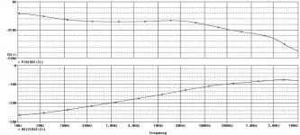
Put a dB probe and a phase probe on the broken loop on R32 and this is the result.
The graph on top is the phase the other is the module.
Is this what you meant so say on your previous post?
Regarding dual jfet for DC tracking.
I am using the dual jfet 2SK389.
Anyways lowering the closed loop gain down to 22dB or so by increasing R32 up to 510ohm, helps to keep the drifting down to 3-4mV or so.
I was planning on zero the DC offset through R4 with a trimmer in that position.
I have never tried the configuration you described.
Would it work better?
I gave up with the DC regulation because i am scared that with component aging it would need to be tracked periodically.
An output DC cap would avoid this problem (i am thinking if the preamplifier would be connected to a DC coupled system with possible damage to speakers)
Attachments
Maybe try a 150 USD soundcard (EMU Tracker Pre) and the free ARTA and you have it all.
Sigurd
Sigurd
Stefanoo said:oh my goodness.....good for you!!
It's nice to have all these equipment available.
I wish i would have more.
In the near future i might consider buying a HP sound analyzer.
I am making more measurement on the circuit (i will attach the schematic).
For this test i took off the capacitors that are responsable for the RIAA equalization
Probing across R4 shows that when Q3 turns on the input stage starts to be loaded and there is distortion.
Might this be due to the input capacitance of Q3 (IRF9610) that loads the cascoded negative output of the 2SK389?
Is there any suggestion to solve this problem?
Sigurd Ruschkow said:Maybe try a 150 USD soundcard (EMU Tracker Pre) and the free ARTA and you have it all.
Sigurd
Hi Sigurd,
I am not an expert of soundcards.
I used to use Visual Analyzer with my integrated soundcard but it's not so silent.
Noise floor is about 95dB i think.
Few months ago I was actually thinking of getting the Emu0202.
Nevertheless it is not so compatible with Win Vista that I have on my laptop and so i ended up leaving the idea.
I noticed that the Emu Tracking is compatible with the new systems ad this is good.
Apparently, the 0202 and Traking have the same features.
192KHz sampling and same noise floor SNR and so on.
With 192KHz it is possible to run a spectrum analysis up to 90KHz or so which is very good.
How long have you been using the soundcard for your analysis for?
Can you tell me some cool analysis that is possible to run with the Soundcard?
I mean....i think that in order to have a Distortion analysis I would still need a very low distortion signal generator, right?
Usually this comes along with the audio system as HP339 or others.
I believe in these soundcards thing as i think are inexpensive and useful tools but...i mean i see lots of people who are against these solutions who reject soundcards.
I mean....comparing for example an expensive piece of equipment as HP339 (i am not mentioning AP system as the comparison would be as comparing tomato vs banana 🙂 )...or other similar sound system......what are the main differences?
I am curious....
i might end up buying the soundcard you mentioned ....
With 24-bit soundcards you will get a noise floor around -130 - -140dB.
Please read more in the Dispre thread.
The signal generator is simply the DA-part in the sound card.
No need for an external soundcard.
Sigurd
Please read more in the Dispre thread.
The signal generator is simply the DA-part in the sound card.
No need for an external soundcard.
Sigurd
Stefanoo said:
Hi Sigurd,
I am not an expert of soundcards.
I used to use Visual Analyzer with my integrated soundcard but it's not so silent.
Noise floor is about 95dB i think.
Few months ago I was actually thinking of getting the Emu0202.
Nevertheless it is not so compatible with Win Vista that I have on my laptop and so i ended up leaving the idea.
I noticed that the Emu Tracking is compatible with the new systems ad this is good.
Apparently, the 0202 and Traking have the same features.
192KHz sampling and same noise floor SNR and so on.
With 192KHz it is possible to run a spectrum analysis up to 90KHz or so which is very good.
How long have you been using the soundcard for your analysis for?
Can you tell me some cool analysis that is possible to run with the Soundcard?
I mean....i think that in order to have a Distortion analysis I would still need a very low distortion signal generator, right?
Usually this comes along with the audio system as HP339 or others.
I believe in these soundcards thing as i think are inexpensive and useful tools but...i mean i see lots of people who are against these solutions who reject soundcards.
I mean....comparing for example an expensive piece of equipment as HP339 (i am not mentioning AP system as the comparison would be as comparing tomato vs banana 🙂 )...or other similar sound system......what are the main differences?
I am curious....
i might end up buying the soundcard you mentioned ....
Stefanoo said:
Unfortunately Self likes Class AB and high feedback design both things that i don't really like.
I have broken the loop as you suggested (i took the MC part off as i am evaluating only the stability for the 3 stage design and took the capacitors responsable for the RIAA C66/C18 off of the scene for now).
I have put an AC source at the gate of J1A and at the gate of J1B as well.
Put a dB probe and a phase probe on the broken loop on R32 and this is the result.
The graph on top is the phase the other is the module.
I was planning on zero the DC offset through R4 with a trimmer in that position.
I have never tried the configuration you described.
Would it work better?
Stefanoo, good progress being made. You only need to connect the Pspice generator to J1B gate. J1A input should be grounded by connecting the input to 0V. The dB plot should start off high and decrease with frequency, and should eventually cross 0dB.
You currently have no real control of open loop gain in your circuit, and so you do have a high overall feedback design like Mr. Self's! The addition of one resistor could solve this (clue - one end connects to Q6 collector).
R4 will not directly trim DC offset, but I want you to figure out why.
R56 needs to be bypassed with a capacitor - why is this?
Hi Paul,
thank you very much for your appreciation.
I will reply to you once upon a time.
First let me start with the loop gain and phase.
Reading through some posts.....bannngg.... i found this one that helped i think (link is this one below)
http://www.diyaudio.com/forums/showthread.php?postid=1710530#post1710530
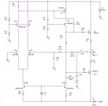
Thus, I followed the indications written there to evaluate loop gain and phase and the schematic is the following:
thank you very much for your appreciation.
I will reply to you once upon a time.
First let me start with the loop gain and phase.
Reading through some posts.....bannngg.... i found this one that helped i think (link is this one below)
http://www.diyaudio.com/forums/showthread.php?postid=1710530#post1710530
Thus, I followed the indications written there to evaluate loop gain and phase and the schematic is the following:
Attachments
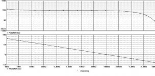
...and the simulation result.
Speaking now of:
1) R4: it zeroes out the DC.
On the prototype i have built if i adjust the value, DC at the output changes.
The current mirror Q16A fixes Bias current for the VAS stage and along with R56 the the bias for the output stage as well.
Lets pretend everything is perfect and there are 0V at the output.
Now, if i adjust R4, the current flowing on M1 has to be the same.
So the differential will start unbalance the current on the two halves till this condition is restored.
More or less current will flow at the output devices Q7 and output will float.
This mechanism apparently works but if you say so there must be something i don't catch: any help 🙂 ?
2) bypassing R56 should make bias more stable and DC drifting would reduce i guess, is it correct?
3)Speaking of o/l gain.
In order to lower the o/l gain i can lower the gm of the differential stage by lowering the current on the tail, right?
But is well known that jfets sound much nicer at higher Id.
I would like to find a method to measure the open loop gain and thus evaluate how much feedback is injected on the circuit.
Self briefly shows a method on page 70 but it don't completely understand it.
It takes the negative and positive input of the differential input pair, buffers them and measures the output divided the differential input at different frequencies.
But it does this with the Feedback network connected!
Thus...is this is a closed loop gain or the open?...i don't understand.
4) Still on the Self's book, he shows that instead of having the resistor loading the diff pair, a current mirror version has supposedly a way lower HF distortion BUT increases the O/L gain...which i guess it is bad.
Would this a better solution anyways?
Edit:
You said it is possible take control over the open loop gain by adding a resistor at Q6's collector, but i don't understand this thing.
May you explain this a little more?
Attachments
Sigurd Ruschkow said:With 24-bit soundcards you will get a noise floor around -130 - -140dB.
Please read more in the Dispre thread.
The signal generator is simply the DA-part in the sound card.
No need for an external soundcard.
Sigurd
I have read the thread you suggested.
Thanks it is an interesting subject.
Although you suggested an even better soundcard as Emu1515, i can't find it.
You also mentioned there are consumers and professional soundcars.
I would be interested on the latter.
Can you give some advice on a very good soundcard, something better than Emu track?
You also said that result depends upon software that matches the card.
You mentioned Arta and SpectraPlus...i mean....isn't there a software....just one...that can do everything needed for audio stuff?
Like spectral analysys distortion analysis....i mean why would you use 2 SW: do they have different features?
Just a stupid question...since i don' have any experience on these soundcards as i said:
syn used his expensive HP to check the RIAA.
He plotted frequency response and with the option built in (the math) he could evaluate the absolute difference.
Is it possible with JUST the soundcard?
You said that Signal generator is the DA part of the card, so is it possible to run a frequency response?
Is the signal generator made with the soundcard enough precise/flat/low distortion on the bandwidth of interest (20Hz-40KHz..or even less....)?
thank you very much for the attention
paul joyce said:
..... The addition of one resistor could solve this (clue - one end connects to Q6 collector).
you meant to add an high value resistor, something like 220K on the local feedback network of the VAS stage, right?
This could lower the global feedback of 20dB.
Just one curiosity:
have you ever had experience on a balance VAS configuration?
Stefanoo said:Hi Paul,
thank you very much for your appreciation.
I will reply to you once upon a time.
First let me start with the loop gain and phase.
Reading through some posts.....bannngg.... i found this one that helped i think (link is this one below)
http://www.diyaudio.com/forums/showthread.php?postid=1710530#post1710530
Thus, I followed the indications written there to evaluate loop gain and phase and the schematic is the following:
While the method is correct, something is still not right in the results you got.
- V21 should be VAC rather than VSIN (as it is currently, in your schematic). Set the VAC amplitude to 1V
- Set C24 to a very small value and redo the plot as an AC simulation from 1Hz to 10MHz.
This would be a good starting point. Then increase C24 starting with 10pF in 10pF increments until you get a phase margin of 80-100 degrees.
Repost if still in doubt.
EMU1616m is the best I know of.
WinAudioMLS will do everything you want. Made by Dr Jordan Design in Germany. They also make a signal generator that has RIAA curve.
ARTA (and STEPS) is a very very good software. Do not underestimate it.
Please try the demos and you will learn what they can.
Also try RMAA 6.
To make a sweep you need a soundcard and a signal generator software, or just take a CD with a sweep on it and use your DVM.
Sigurd
Stefanoo said:
I have read the thread you suggested.
Thanks it is an interesting subject.
Although you suggested an even better soundcard as Emu1515, i can't find it.
You also mentioned there are consumers and professional soundcars.
I would be interested on the latter.
Can you give some advice on a very good soundcard, something better than Emu track?
You also said that result depends upon software that matches the card.
You mentioned Arta and SpectraPlus...i mean....isn't there a software....just one...that can do everything needed for audio stuff?
Like spectral analysys distortion analysis....i mean why would you use 2 SW: do they have different features?
Just a stupid question...since i don' have any experience on these soundcards as i said:
syn used his expensive HP to check the RIAA.
He plotted frequency response and with the option built in (the math) he could evaluate the absolute difference.
Is it possible with JUST the soundcard?
You said that Signal generator is the DA part of the card, so is it possible to run a frequency response?
Is the signal generator made with the soundcard enough precise/flat/low distortion on the bandwidth of interest (20Hz-40KHz..or even less....)?
thank you very much for the attention
Stefanoo, the bode plot tells us some useful information:Stefanoo said:...and the simulation result.
1) R4: it zeroes out the DC.
On the prototype i have built if i adjust the value, DC at the output changes.
The current mirror Q16A fixes Bias current for the VAS stage and along with R56 the the bias for the output stage as well.
Lets pretend everything is perfect and there are 0V at the output.
Now, if i adjust R4, the current flowing on M1 has to be the same.
So the differential will start unbalance the current on the two halves till this condition is restored.
More or less current will flow at the output devices Q7 and output will float.
2) bypassing R56 should make bias more stable and DC drifting would reduce i guess, is it correct?
3)Speaking of o/l gain.
In order to lower the o/l gain i can lower the gm of the differential stage by lowering the current on the tail, right?
But is well known that jfets sound much nicer at higher Id.
I would like to find a method to measure the open loop gain and thus evaluate how much feedback is injected on the circuit.
Self briefly shows a method on page 70 but it don't completely understand it.
It takes the negative and positive input of the differential input pair, buffers them and measures the output divided the differential input at different frequencies.
But it does this with the Feedback network connected!
Thus...is this is a closed loop gain or the open?...i don't understand.
4) Still on the Self's book, he shows that instead of having the resistor loading the diff pair, a current mirror version has supposedly a way lower HF distortion BUT increases the O/L gain...which i guess it is bad.
Would this a better solution anyways?
Edit:
You said it is possible take control over the open loop gain by adding a resistor at Q6's collector, but i don't understand this thing.
May you explain this a little more?
1) The compensation of C24 (or C3 in your original schematic) is VERY agressive, since the amplifier open loop resonse is rolling off below 1Hz! If you start your plot at 0.1Hz (or even lower) you should see the gain starting to flatten out.
2) The dB value of the loop gain is how much feedback you have at each frequency.
3) Where the loop gain falls to 0dB, you have -90 degrees of phase shift - so phase margin is 90 degrees. You need to try this at the other end of the RIAA gain extreme, by reducing the feedback resistors to 1/100th of their current values.
The dc voltage across R4 is fixed by dc feedback for a given output voltage. Changing R4 will force an imbalance in current in the differential pair, but using this to tweak offset is crude.
Better to put a pot in between the input pair source connections with the wiper to the current source. This allows the input offset voltage to be directly controlled, and the resistance will also reduce DC drift, and reduce the Gm and improve the linearity of the input stage. Self shows this in his book, although he is using bipolars.
R56 should be bypassed so that the output gates see the same impedance at high frequencies, as this resistor is only there for DC bias.
Adding a resistor to ground at Q6 collector will allow you to define the open loop voltage gain. Currently, this impedance is only defined by the transistors themselves. If you connected a resistor from Q6 collector to J1B gate via cap, you could then have an internal feedback loop to define the open loop gain.
You can also add a resistor in series with Q3 source to reduce the Gm of the VAS, which will also reduce the DC drift.
Doug Self's technique of meausuring the voltage across the diff pair inputs can be done (in a closed loop, this is the error voltage, so dividing the output voltage by this gives you the open loop gain. It's a very tiny voltage though, so would have to be amplified. Example - if your open loop gain is 100dB, an output voltage of 10V would mean this differential voltage is only 0.1mV!
the signal at R4 is the amplified error signal, so it's a little easier to see.
Doug Self's idea of loading differential pair output with a current mirror allows you to obtain the full gain of the diff pair (i.e Gm x R4 instead of Gm/2 x R4). Personally, I like a Differential VAS as it is more linear than the single ended version, and in your case has less DC drift.
Sigurd Ruschkow said:EMU1616m is the best I know of.
WinAudioMLS will do everything you want. Made by Dr Jordan Design in Germany. They also make a signal generator that has RIAA curve.
ARTA (and STEPS) is a very very good software. Do not underestimate it.
Please try the demos and you will learn what they can.
Also try RMAA 6.
To make a sweep you need a soundcard and a signal generator software, or just take a CD with a sweep on it and use your DVM.
Sigurd
Hi Sigurd,
thank you for your advice.
I am going to purchase the EMU Track as i have checked the 1616m as you suggested on the other thread and specs are very high as well as the price.
I think that the track is a good tool for a reasonable price.
Speaking of software....i have the SpectraPlus do you think that the WinAudio would be even better?
I will check out tomorro as it is 12.38AM.
Thank you very much.
Best,
paul joyce said:
Stefanoo, the bode plot tells us some useful information:
1) The compensation of C24 (or C3 in your original schematic) is VERY agressive, since the amplifier open loop resonse is rolling off below 1Hz! If you start your plot at 0.1Hz (or even lower) you should see the gain starting to flatten out.
2) The dB value of the loop gain is how much feedback you have at each frequency.
3) Where the loop gain falls to 0dB, you have -90 degrees of phase shift - so phase margin is 90 degrees. You need to try this at the other end of the RIAA gain extreme, by reducing the feedback resistors to 1/100th of their current values.
The dc voltage across R4 is fixed by dc feedback for a given output voltage. Changing R4 will force an imbalance in current in the differential pair, but using this to tweak offset is crude.
Better to put a pot in between the input pair source connections with the wiper to the current source. This allows the input offset voltage to be directly controlled, and the resistance will also reduce DC drift, and reduce the Gm and improve the linearity of the input stage. Self shows this in his book, although he is using bipolars.
R56 should be bypassed so that the output gates see the same impedance at high frequencies, as this resistor is only there for DC bias.
Adding a resistor to ground at Q6 collector will allow you to define the open loop voltage gain. Currently, this impedance is only defined by the transistors themselves. If you connected a resistor from Q6 collector to J1B gate via cap, you could then have an internal feedback loop to define the open loop gain.
You can also add a resistor in series with Q3 source to reduce the Gm of the VAS, which will also reduce the DC drift.
Doug Self's technique of meausuring the voltage across the diff pair inputs can be done (in a closed loop, this is the error voltage, so dividing the output voltage by this gives you the open loop gain. It's a very tiny voltage though, so would have to be amplified. Example - if your open loop gain is 100dB, an output voltage of 10V would mean this differential voltage is only 0.1mV!
the signal at R4 is the amplified error signal, so it's a little easier to see.
Doug Self's idea of loading differential pair output with a current mirror allows you to obtain the full gain of the diff pair (i.e Gm x R4 instead of Gm/2 x R4). Personally, I like a Differential VAS as it is more linear than the single ended version, and in your case has less DC drift.
Thanks a lot for your reply.
I will carefully read it tomorrow and post back.
Best,
There is a demo of WinAudio which you can DL. Try both out and see which software you prefer. The cost of these softwares is about 10-40X the HW cost.
ARTA+STEPS is about 100E only.
Sigurd
ARTA+STEPS is about 100E only.
Sigurd
Stefanoo said:
Hi Sigurd,
thank you for your advice.
I am going to purchase the EMU Track as i have checked the 1616m as you suggested on the other thread and specs are very high as well as the price.
I think that the track is a good tool for a reasonable price.
Speaking of software....i have the SpectraPlus do you think that the WinAudio would be even better?
I will check out tomorro as it is 12.38AM.
Thank you very much.
Best,
Sigurd Ruschkow said:There is a demo of WinAudio which you can DL. Try both out and see which software you prefer. The cost of these softwares is about 10-40X the HW cost.
ARTA+STEPS is about 100E only.
Sigurd
As soon as the soundcard will get here I will try them both.
The RIAA generator is a very nice tool.
Just wondering:
Is it possible with SpectraPlus to do a post analyze of the frequency response and build a RIAA math function and plot the error?
- Status
- Not open for further replies.
- Home
- Amplifiers
- Solid State
- Moving Coil preamp design