try moving output node somewhere else
didn't tried these tricks with PapaSit , but SUFI-SIT sim (#443) is best arangement I could get , with this brain
I did sims of DEFiSIT , to grasp as much I can , but didn't tried to make it better than it is
didn't tried these tricks with PapaSit , but SUFI-SIT sim (#443) is best arangement I could get , with this brain
I did sims of DEFiSIT , to grasp as much I can , but didn't tried to make it better than it is
try moving output node somewhere else
didn't tried these tricks with PapaSit , but SUFI-SIT sim (#443) is best arangement I could get , with this brain
I did sims of DEFiSIT , to grasp as much I can , but didn't tried to make it better than it is
How does the actual sound compare at the different positions?
Actually it is CLASS-A, PUSH-PUSH!
just realized that there is new class of amplifier output stage , invented by Pa
∀ Class
How does the actual sound compare at the different positions?
why should I try something which is so obviously worse in simulations ?
worse means - pretty much same THD spectra , but worse in level
as you pretty well know , one must have specific level of trust in simulations , not just based on general verity of simulations itself , but also in ability of operator* and , no less important, comparison of sim results with comparable constructions already confirmed in vivo
*which is , in case of Mighty ZM , always questionable
Last edited:
I do not understand the technical contents at all, so I cannot do anything about it. 🙂🙂
I thought that I can make the circuit from infant idea look more like the real one. Until I am given some easy-to-build circuit this is all I can think of.
By the way, I replaced the big FET from follower circuit with THF51-S and it is much better to my ears. (my only measurement tool..) It just raised my expectation about DEFiSIT. Maybe I should just buy SIT-3.
Attachments

Last edited:
buy SIT-3 , that good bothfor Papa and for you
that way your measurement equipment will get pretty good reference ..... and you can proceed with fun , building
🙂
your cute back-of -napkin schematic is practically same as my SUFI-SIT amp , few posts up (#443) ..........
try to introduce same source resistors and output arrangement , re-bias , then listen
editedit: hope you did heavy filtering in your bias voltage resistance network , to tame ripple coming from negative rail
Last edited:
I already did order SIT-3. But my order was not firmy acknowledged.
I do appreciate the real one I had F1 F2 F7. I built Zen SOZ...
Are you there bad Papa? Put me on the order list so that build and compare and have fun...😡
I even changed my speakers to Altec after reading some review on Positive Feedback.🙁
I do appreciate the real one I had F1 F2 F7. I built Zen SOZ...
Are you there bad Papa? Put me on the order list so that build and compare and have fun...😡
I even changed my speakers to Altec after reading some review on Positive Feedback.🙁
Yeh, that would be nice, with sufficient volume for the woofers. Valencia and Flamenco..these cabinets just do not have enough volume for those 15" woofer I think.
Maybe someday, a MLTL with 604 coaxial unit. For now, I am trying to get to know this Valencia. 🙂
I saw your circuit #443, I do not understand the role of D1 D2 D3, how you bias upper SIT and low FET, not to mention the function of optocoupler.
Without U3, it is still functional I think, then how you get the bias voltage, why those D1 D2 D3 are back to back? 😕
Last edited:
just take source resistors for mosfet and try them
observe where output node is
regarding biasing , there is recently quoted explanation how M2 biasing is working , but can't recall in which thread ...... maybe M2
for your needs , no benefit in complicating it , at least not for now
observe where output node is
regarding biasing , there is recently quoted explanation how M2 biasing is working , but can't recall in which thread ...... maybe M2
for your needs , no benefit in complicating it , at least not for now
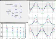
What I do not understand here.....
In my simulation the P channel shows the distortion and the SIT curve is "good"
Also my SIT vurve is the big one and the P channel curve the smaller one,
All vice versa...
No me was vice versa!
😱
and I am just fighting with this effect in Spice. When I go higher with the current to 2A things get better.
Like this at 18W/8Ohm and 2A bias.
Attachments
I told ya .......... observe sources , or drains - but not mixed to avoid confusion
then current through load
it is ∀ Class
🙂
then current through load
it is ∀ Class
🙂
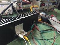
I took some time to wire these and tried. 2SJ28 and IRFP150N giving the voltage below, Vgs 4.19V @1.5A 24V.
But I do not know what the heaven these mean... It looks usable to me, with capacitors before and after the circuit. 😕
Maybe I will wire another channel and see how it sounds.
But I do not know what the heaven these mean... It looks usable to me, with capacitors before and after the circuit. 😕
Maybe I will wire another channel and see how it sounds.
Attachments
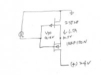
I wired the second one, and it gives 4.5 Vgs 1.5A but the voltage distribution is like 1:5 ratio..... no good and I now begin to see what is this about 🙂
- Home
- Amplifiers
- Pass Labs
- Most Greedy Boy, of them all... or (there is no) DEFiSIT of Papa's Koans