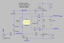
in this circuit , Schade feedback net signal is approx. 1/11 of input signal , which is logical , taking in account resistor values of 1K and 10K .....
accordingly (loss in entire circ) Schade feedback net signal is 1/10 of output signal
accordingly (loss in entire circ) Schade feedback net signal is 1/10 of output signal
And it so happened that you give the rest of us greedy poor boyz (that did not have the SITs) another way to taste the delicious sonic signature..... just playin' with M2 ......

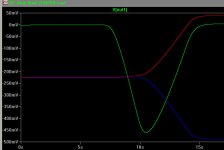
I did few measurements last night and discovered that I made a mistake by looking at it only from AC point of view. Measurements confirmed what you say and the sim software wasn't against it too. The pic clearly shows that such a connection causes clear dependability of Id on Vds (V1) change only. Every curve represents a different value of Vgs (V2). I stand corrected. Thank you.It does not. The Schade connection is still there, as the same amount of
current flows through that resistor in either mode.
Of course, the effect is suppressed by all the degeneration offered by
common-drain operation.

Attachments
Thanks for sharing this, I think that in addition to you, many in this forum are surprised by this.
Have you played with different values or definitely 10k and 1k is the choice?
Thanks
Have you played with different values or definitely 10k and 1k is the choice?
Thanks
I don't think so - I mean, when you really look at it, it's hard to miss it (but I missed it anyway) 😀... many in this forum are surprised by this.
They are just a voltage divider, so changing their ratio will change the curve's angle i.e. "triode's" gm. Here is 10k/1k compared to 10k/3k.Have you played with different values or definitely 10k and 1k is the choice?
Attachments
of course , it would be best to have them aligned perfectly pitched , at angle of 45deg , in area of interest .... speaking strictly of part , out of entire amp context

of course , it would be best to have them aligned perfectly pitched , at angle of 45deg , in area of interest .... speaking strictly of part , out of entire amp context
What? And miss out on all that lovely distortion?
😱
bugging me for few weeks ...... something familiar and I still can't remember arousing association ...... and I finally got it , in a moment when I (de)crippled upper mosfet in M2, for SEF amp
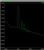
DEF output reminds me of The Blind Leading the Blind - Wikipedia

good old PB

DEF output reminds me of The Blind Leading the Blind - Wikipedia
good old PB
Last edited:
few things tackled (proper dissipation of power resistors , back to kosher bias circ guarding elements)
this one can go to prototype
this one can go to prototype
Attachments
Last edited:
If I'm not mistaken, it simmed to a positive phase H2, so may need to reverse speaker wire polarity for negative phase H2 signature, easy enough to verify.... this one can go to prototype
Simply look at the negative or positive sign of the normalized phase of H2 at the log file. Just remember that for steady state sinewave, 360° is 0° and 260° is -100° and you are fine.
In case you want to view the distortion residual waveform, you can use the tool jcx shared at Spice simulation post #361.
In case you want to view the distortion residual waveform, you can use the tool jcx shared at Spice simulation post #361.
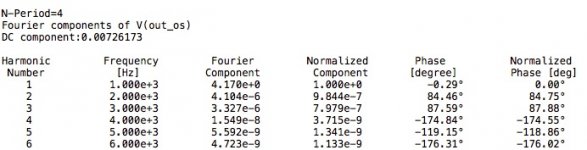
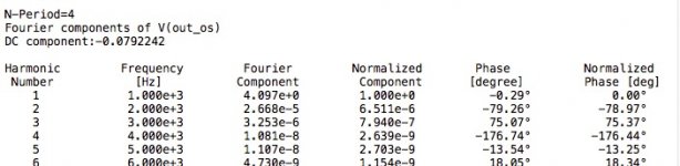
Left positive, right negative, but also try more periods like 16 or 32 to get more accurate prediction. I usually use something like .four 1k 9 -1 V(out_os) directive, the -1 includes all captured data in the FFT calculation instead of just the last period and the 9 limits calculation to the 9th harmonic.
Zen Mod, I have played a single channel of your amp schematic at post #170. I biased it at 1.48 amps, by changing the source resistor to 1.1 ohm. Did not use the offset pot, had an offset of 1.2 volts and so used an output capacitor of 4700uF.
The sound is more lush compared to the original M2 Output configuration. Overall it is very nice but gets a bit shouty with average recordings and complex passages.
M2 is cleaner and separation of instruments is very good.
The sound is more lush compared to the original M2 Output configuration. Overall it is very nice but gets a bit shouty with average recordings and complex passages.
M2 is cleaner and separation of instruments is very good.
try decreasing source resistance to 0.66 and decreasing R7 (even to 0R) ...... nothing wrong with more heat in mosfets .... up to 35W is for eternity , and 40W for 0.75 eternity (which is still pretty good number 🙂 )
after that , playing with tiny changes of 1K gate resistor of upper mosfet , with offset correction each time
and , of course that M2 is cleaner ........... this is game of controlled increase of THD 🙂
after that , playing with tiny changes of 1K gate resistor of upper mosfet , with offset correction each time
and , of course that M2 is cleaner ........... this is game of controlled increase of THD 🙂
Using multi way speaker?... Overall it is very nice but gets a bit shouty with average recordings and complex passages. ...
- Home
- Amplifiers
- Pass Labs
- Most Greedy Boy, of them all... or (there is no) DEFiSIT of Papa's Koans