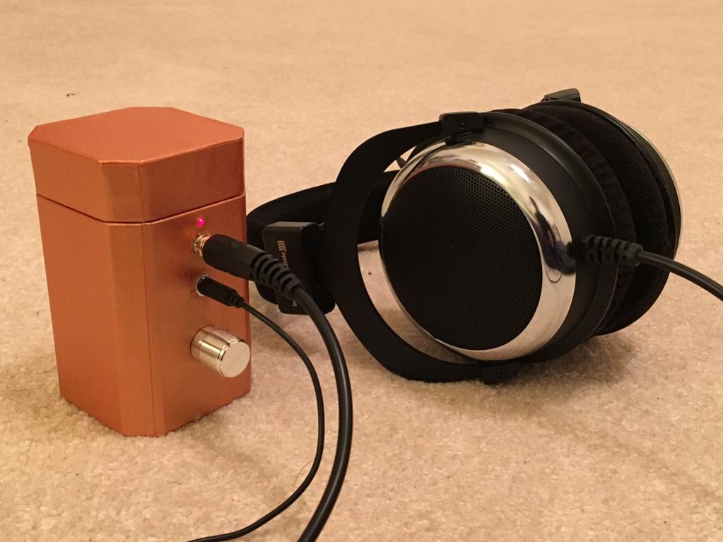
The above amp now simulated "as-built" shows a terrific harmonic distortion profile, which explains why my buddy preferred it immediately over a Super CMOY using an OPA1688. He was so happy listening to it, I gave him the amp as a new years' present. 🙂
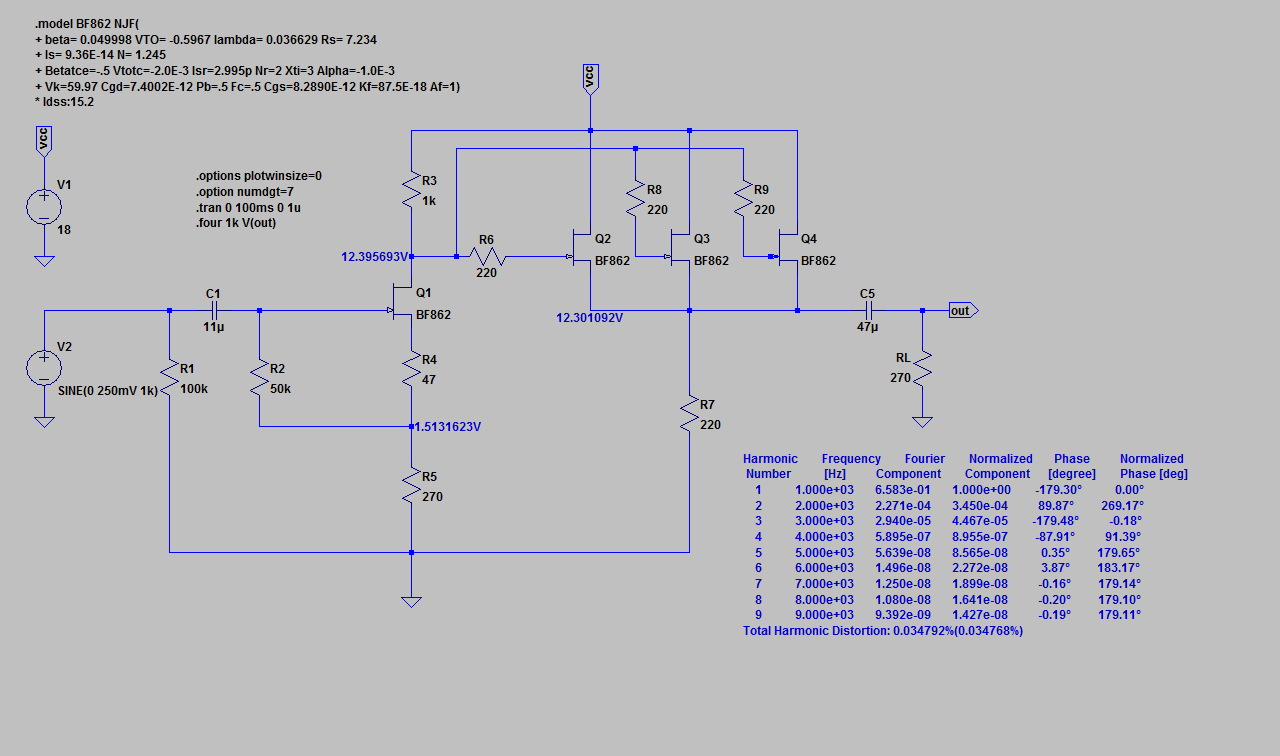
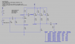
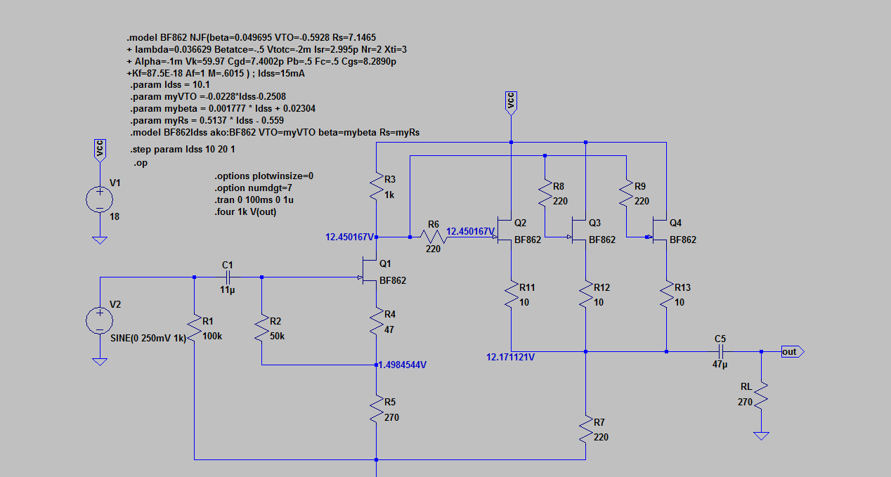
Schematic and HD analysis with 0.035% THD at 1.2v p-p output, mostly H2 and very little H3, and nothing else:
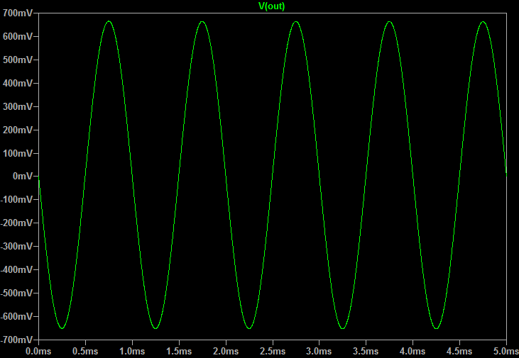
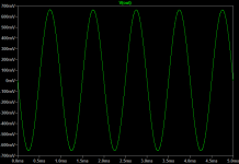
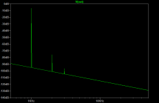
1k sine wave at 1.2v p-p:
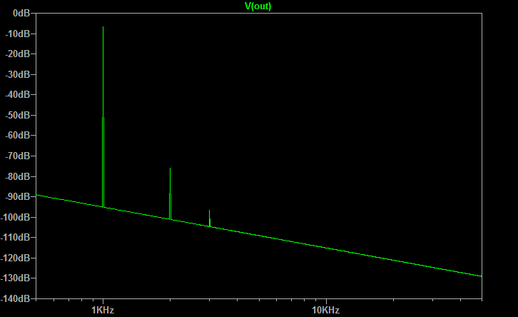
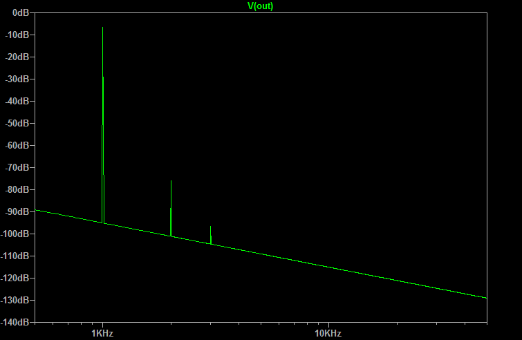
FFT:
At more modest, normal listening levels of 500mV output p-p, THD is only 0.014%:
Harmonic Frequency Fourier Normalized Phase Normalized
Number [Hz] Component Component [degree] Phase [deg]
1 1.000e+03 2.634e-01 1.000e+00 -179.30° 0.00°
2 2.000e+03 3.602e-05 1.368e-04 89.85° 269.15°
3 3.000e+03 1.861e-06 7.067e-06 -179.47° -0.17°
4 4.000e+03 1.758e-08 6.674e-08 -58.31° 120.99°
5 5.000e+03 7.724e-09 2.933e-08 -0.09° 179.21°
6 6.000e+03 6.033e-09 2.291e-08 -0.15° 179.15°
7 7.000e+03 5.088e-09 1.932e-08 -0.23° 179.07°
8 8.000e+03 4.369e-09 1.659e-08 -0.26° 179.04°
9 9.000e+03 3.800e-09 1.443e-08 -0.27° 179.03°
Total Harmonic Distortion: 0.013697%(0.013636%)
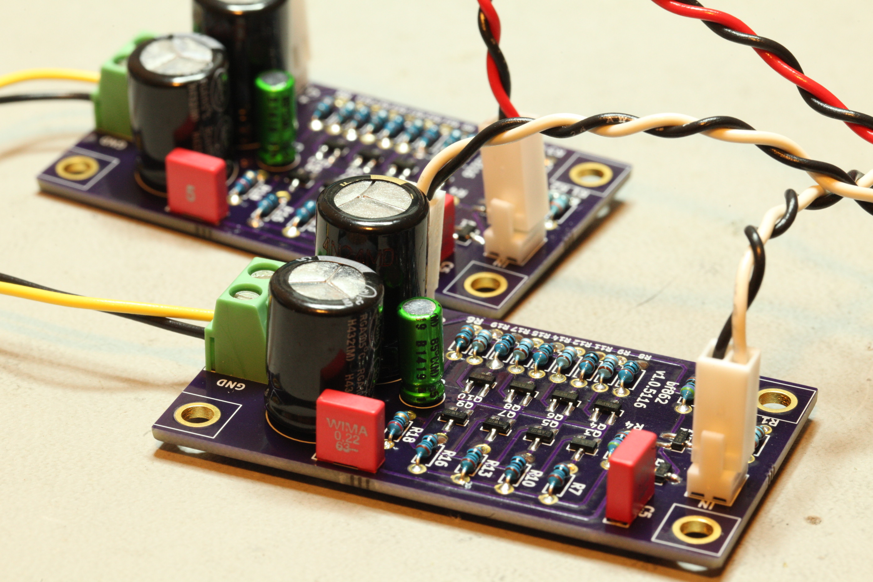
I think this 4 BF862 head amp is superb bang for the buck. This amp can be made for literally under $3. 🙂
Attachments

Last edited:
X (as Hugh has forever named you!) - coming together nicely - did you try out the switcher supply with a simple bcxxx C-Mx on this one?
I had a strange idea (with no theory or anything behind it!) so don't laugh -
What happens if/when you add some small local degeneration resistors to those output jfets just like a power amp?
I had a strange idea (with no theory or anything behind it!) so don't laugh -
What happens if/when you add some small local degeneration resistors to those output jfets just like a power amp?
X (as Hugh has forever named you!) - coming together nicely - did you try out the switcher supply with a simple bcxxx C-Mx on this one?
I had a strange idea (with no theory or anything behind it!) so don't laugh -
What happens if/when you add some small local degeneration resistors to those output jfets just like a power amp?
Actually, Cal was the first to call me X over in the Full Range Forum. 🙂
I had degen resistors at one point but this BF862 has such a good transconductance that we try to eliminate it and match the JFETs to get the best punch for bass. I can run a quick sim with say 0.22R's and see what happens.
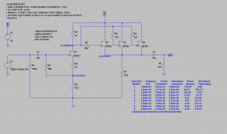
Here is the sim with 0.22R's added:
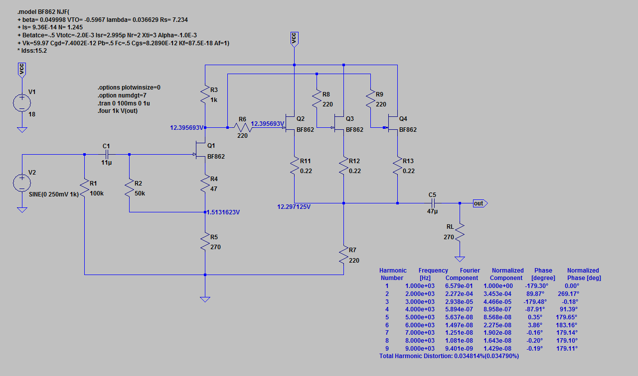
Harmonic Frequency Fourier Normalized Phase Normalized
Number [Hz] Component Component [degree] Phase [deg]
1 1.000e+03 6.579e-01 1.000e+00 -179.30° 0.00°
2 2.000e+03 2.272e-04 3.453e-04 89.87° 269.17°
3 3.000e+03 2.938e-05 4.466e-05 -179.48° -0.18°
4 4.000e+03 5.894e-07 8.958e-07 -87.91° 91.39°
5 5.000e+03 5.637e-08 8.568e-08 0.35° 179.65°
6 6.000e+03 1.497e-08 2.275e-08 3.86° 183.16°
7 7.000e+03 1.251e-08 1.902e-08 -0.16° 179.14°
8 8.000e+03 1.081e-08 1.643e-08 -0.20° 179.10°
9 9.000e+03 9.401e-09 1.429e-08 -0.19° 179.11°
Total Harmonic Distortion: 0.034814%(0.034790%)
About the same - but would mean JFETs don't need to be as carefully matched.
Attachments
Last edited:
There's room for a track mod to physically try them out?
Maybe go for something like a 1R5 and add a // one to reduce to this 0.2R in stages - just an idea about the sound of it - not very scientific at all, I'm afraid.
Maybe go for something like a 1R5 and add a // one to reduce to this 0.2R in stages - just an idea about the sound of it - not very scientific at all, I'm afraid.
I'll have to build new amp as I just gave that amp to my friend. I was planning on making another batch. This time with tiny footprint to fit in Altoids mint tin for a true pocket class A amp. I know it runs on two 9v batteries well. Have to wait for my order of 50 BF862's to come in. I'm about all out of them now. Will need to match them and find two triplets again. I will leave space for the degeneration resistors though. Maybe 2.2R even?
Last edited:
the simulator adopts an identical model for each jFET type.
Placing identical models in parallel will result in a prediction that assumes identical behaviour.
There will be no prediction for unmatched parameters.
When you build the real thing there will be some unsimulated behaviour.
I think that's why Aksa suggested the avoidance of many paralleled output sets.
A real world test is necessary😉the simulator adopts an identical model for each jFET type.
Placing identical models in parallel will result in a prediction that assumes identical behaviour.
There will be no prediction for unmatched parameters.
When you build the real thing there will be some unsimulated behaviour.
I think that's why Aksa suggested the avoidance of many paralleled output sets.
Check out these 10 x BF862 SE Class A amp boards by Mlackey:
http://www.diyaudio.com/forums/head...class-headamp-without-heat-7.html#post4941133
http://www.diyaudio.com/forums/head...class-headamp-without-heat-7.html#post4941133
the simulator adopts an identical model for each jFET type.
You can simulate the impact of non-identical devices if you like.
I do it like this.
You can use your soundcard and e.g. ARTA or similar software to look at the real harmonic profile.When you build the real thing there will be some unsimulated behaviour.
X,
Rule of thumb might assume Vgs would change +/-0.1V.
Since we gun for 10mA Id on each this delivers a source resistor of 10R.
You can also figure the gm, which is around 30mS. Take the reciprocal, 33, and set the source resistor of one third.
HD
Rule of thumb might assume Vgs would change +/-0.1V.
Since we gun for 10mA Id on each this delivers a source resistor of 10R.
You can also figure the gm, which is around 30mS. Take the reciprocal, 33, and set the source resistor of one third.
HD
Thanks for the rule of thumb Hugh. So only if the model shows variances in Vgs and Idss will the 10R source resistors have an effect. This is neat stuff from Elfishi though. I will give detailed variable model a try when I have some time.
I am trying to simulate the variable Idss over in this thread - but not sure if doing it right.
http://www.diyaudio.com/forums/solid-state/296859-ltspice-model-your-bf862-jfets-3.html#post4941729
http://www.diyaudio.com/forums/solid-state/296859-ltspice-model-your-bf862-jfets-3.html#post4941729
ran your numbers, if I'm not mistaken.
With R7 = 220 Ohm your parallel JFETs run in forward bias.
This will get you more distortion and lower Zout.
R7 = 330 Ohm would lower the thd by a third and increase Zout by ca 1 Ohm.
With R7 = 220 Ohm your parallel JFETs run in forward bias.
This will get you more distortion and lower Zout.
R7 = 330 Ohm would lower the thd by a third and increase Zout by ca 1 Ohm.
Attachments
Thanks for running that Elfishi. My 50 BF862's just arrived today so just in time to play around with new amp designs. I am thinking of making one with an SOT23 mosfet.
where do you buy the bf862?
Here:
50PCS BF862 ORIGINAL JFET N-CHAN 20V SOT-23 | eBay
These work well and I have bought from this seller before.
There is a GB for the very nice 10 JFET amp (thanks to Mlackey for nice layout) over in this thread:
http://www.diyaudio.com/forums/head...class-headamp-without-heat-8.html#post4942760
Stereo board with mostly through hole except JFETs:
http://www.diyaudio.com/forums/head...class-headamp-without-heat-8.html#post4942760
Stereo board with mostly through hole except JFETs:
Last edited:
Very good price.Here:
50PCS BF862 ORIGINAL JFET N-CHAN 20V SOT-23 | eBay
These work well and I have bought from this seller before.
Here:
50PCS BF862 ORIGINAL JFET N-CHAN 20V SOT-23 | eBay
These work well and I have bought from this seller before.
Can you read the code on the package?
It's 2AW in big letters then little 65 rotated 90deg. This was the first order. I haven't looked carefully at second order yet. It says 2AW but not sure little text.
- Home
- Amplifiers
- Headphone Systems
- MOSFET Source Follower Headamp