Beautiful things going on in this thread and lovely stuff you got together X!
Now even I feel inspired to build a HPA, my headphones are measuring ca. 40 Ohms, if I would go with the latest schematics presented what would be a suitable resistor value on R7 for mine? 🙂
Thank you, Maiko!
The current value of 100R will give about 117mA bias current. I think 40ohm headphones probably need double that so go with the 47R originally suggested by Hugh. That will give you circa 230mA bias current. When I get back to my computer I can run a sim at 47R and 40R load.
Great if you find time sim it, I myself am currently horribly rusty with sim's as it's very long time ago I used Orcad PSpice, sooner or later I have to jump on the LTspice bandwagon too.
Hopefully the output trany doesn't get too sweaty with my low-ohmish cans.
Hopefully the output trany doesn't get too sweaty with my low-ohmish cans.
I am just learning LTSpice myself. It's not as intuitive as Tina but more folks seem to use it here and more models for interesting devices seem to exist as well. Took me a few days just to figure out how to add a mosfet 🙂
Very nice X,
This is a very simple HPA but it has:
1. Very low THD but better than this a very good profile
2. Robust drive, down to 16R cans and even a speaker at low volume
3. No matching!!
4. Low voltage supply (though PSRR is not good, battery is better)
5. Selectable source resistor for Lo/Hi Z cans
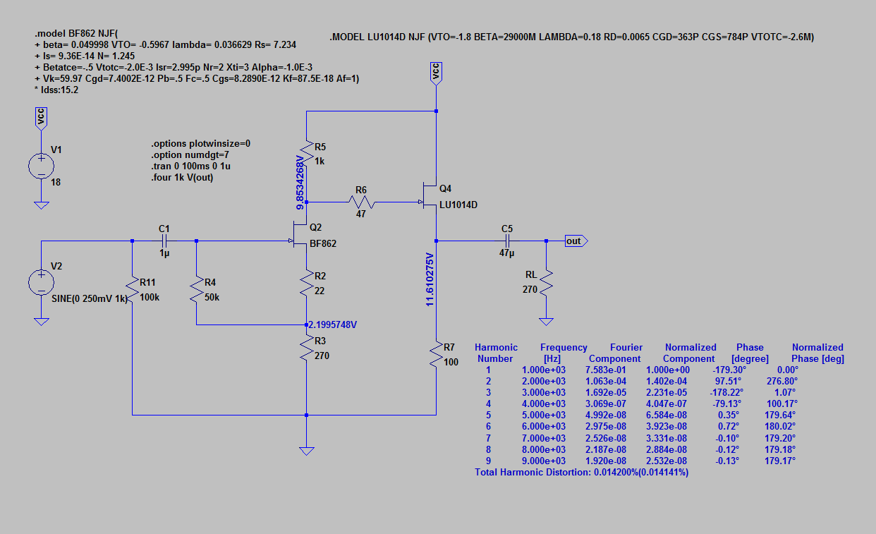
I see you have changed the two source resistors on the BF862 for a higher operating point (9.9mA) so you would need to have a jfet with Idss of 15-18mA. You have wisely reduced R4, the bias resistor, to 50k and found it improves even more resolution..... good thinking.
The LU1014D is coasting; you could take it up to 1A source resistor by replacing R7 100R with a 12R of 15W and then you could easily drive a 8R speaker up to 1W, a bit like a 1626 SET!! The Rdson of the power jfet is so low - less than 10 milliohms - that in low output swings the added distortion is negligible. Given the robustness of this device and the low cost, it would be very hard to beat this in any situation, even ultra high end cans.
HD
This is a very simple HPA but it has:
1. Very low THD but better than this a very good profile
2. Robust drive, down to 16R cans and even a speaker at low volume
3. No matching!!
4. Low voltage supply (though PSRR is not good, battery is better)
5. Selectable source resistor for Lo/Hi Z cans
I see you have changed the two source resistors on the BF862 for a higher operating point (9.9mA) so you would need to have a jfet with Idss of 15-18mA. You have wisely reduced R4, the bias resistor, to 50k and found it improves even more resolution..... good thinking.
The LU1014D is coasting; you could take it up to 1A source resistor by replacing R7 100R with a 12R of 15W and then you could easily drive a 8R speaker up to 1W, a bit like a 1626 SET!! The Rdson of the power jfet is so low - less than 10 milliohms - that in low output swings the added distortion is negligible. Given the robustness of this device and the low cost, it would be very hard to beat this in any situation, even ultra high end cans.
HD
That's already better. See how different that is from the circuit in post # 113 ?This may work pretty well as a very compact HA.
Schematic:
And soon you'll find out that it can be further improved...
That's already better. See how different that is from the circuit in post # 113 ?
And soon you'll find out that it can be further improved...
Would further improvements be in the realm of a few changes of passive components or values or are you talking about adding a CCS?
X,
I looked over the operating points for both jfets.
You have almost exactly -200mV on the BF862 jfet; this should be right in the sweet spot, as defined by NP in his power jfet amp. I would assume this is an Idss around 15mA, and so it's 2/3, again the sweet spot for linear operation.
The power jfet, the LU1014D, as simulated has a bias of (9.853 - 11.610) = -1.757V, which is a little more than NP's linear region on his DLite; his recommendation was -1 to -1.1 volts. Although you have not yet measured it on the proto, the operating point is not as good at the BF862, but most of the additional would be H2. Your LTSpice figures indicate that of your very low 0.014% THD, no less than 99.1% is H2 only. Both active devices deliver very good THD in this absurdly simple circuit, 0.014% is up there with a full on global fb amp.
Thank you for your hard work. I accept that the Juma circuit with 10 jfets is very good, but it's much, much more complex, particularly in light of the required matching. It has been a wonderful experience for both of us - and hopefully a few readers too.
Cheers,
HD
Last edited:
I'm sure you'll try active loading, cascoding etc. soon enough and find out what you like the best.Would further improvements ...
For starters, try C1=2.2uF and C5=470uF (with values as shown in sch. too much of the low frequencies are cut off and the phase shift is way too big, and that's easy to hear).
X,
I looked over the operating points for both jfets.
You have almost exactly -200mV on the BF862 jfet; this should be right in the sweet spot, as defined by NP in his power jfet amp. I would assume this is an Idss around 15mA, and so it's 2/3, again the sweet spot for linear operation.
The power jfet, the LU1014D, as simulated has a bias of (9.853 - 11.610) = -1.757V, which is a little more than NP's linear region on his DLite; his recommendation was -1 to -1.1 volts. Although you have not yet measured it on the proto, the operating point is not as good at the BF862, but most of the additional would be H2. Your LTSpice figures indicate that of your very low 0.014% THD, no less than 99.1% is H2 only. Both active devices deliver very good THD in this absurdly simple circuit, 0.014% is up there with a full on global fb amp.
Thank you for your hard work. I accept that the Juma circuit with 10 jfets is very good, but it's much, much more complex, particularly in light of the required matching. It has been a wonderful experience for both of us - and hopefully a few readers too.
Cheers,
HD
It is indeed perhaps the simplest amp I have seen with predicted performance that is this good. As you say, no PSRR to speak of but with batteries not an issue. If using trafo from mains I would just use cap Mx or laptop SMPS 19v brick.
Which resistors do I adjust to get the bias of the LU1014 down lower? Thanks for all your guidance on this Hugh - it's been a cool and learning filled journey.
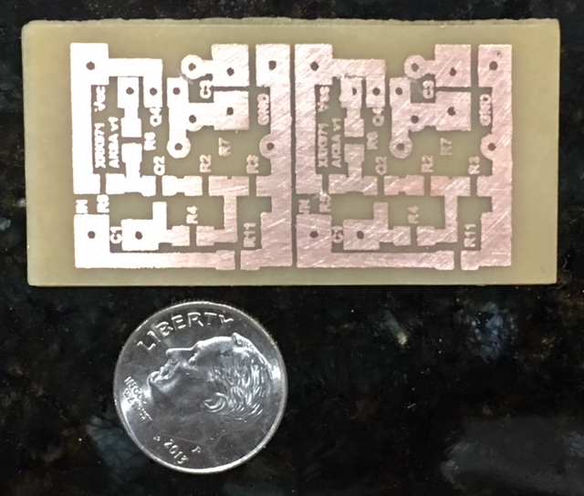
Just finished etching PCB. Will need to trim some bridges with xacto. Board is 25mm x 53mm (sized to fit Altoids tin with room for two 9v batteries). Actual boards are 22mm x 22mm each if made as small as possible. It's a tiny amp. Heatsink may be a problem though. If running 100mA bias that's about almost 4w dissipation for both channels.
Attachments
Last edited:
If you bothered to understand Ohm's Law and read Borbely's article you wouldn't have to ask that.... Which resistors do I adjust to get the bias of the LU1014 down lower? ...
Sorry, but I never understood how people are so willing to wield the soldering iron without a slightest effort invested into understanding how the components and circuit works...
LOL - I guess I forgot to sit down with pencil and paper and do a Kirchoffs law analysis with Ohms law. Oh that's why lazy people like me can get away with using simulators. I meant which knob should I tweak on the sim to get the bias down. 🙂
R5/R3/R7 control the bias.
R5/R3/R7 control the bias.
Juma,
A pity you are sneering at X. If you saw the world more graciously you would realise that even yourself make errors. X is doing great works while you, me and others are idly watching. He needs respect.
Hugh
A pity you are sneering at X. If you saw the world more graciously you would realise that even yourself make errors. X is doing great works while you, me and others are idly watching. He needs respect.
Hugh
Aksa, you misinterpret me for a second time. I begin to think that you are doing it on purpose. I am trying to stimulate him to learn how to catch a fish so he doesn't need to depend on "guru". That's not sneering but a sincere help.
Hi X, where did you find the original LU1014D?
Thiago
Don't know if they are original but seem to work well.
4PC LU1014D LU1014 N- Mosfet Transistor NEW
R3 and R5 control something that you don't want to disturb.
I guess that leaves R7 then but that changes the bias current in addition.
I'm sure you'll try active loading, cascoding etc. soon enough and find out what you like the best.
For starters, try C1=2.2uF and C5=470uF (with values as shown in sch. too much of the low frequencies are cut off and the phase shift is way too big, and that's easy to hear).
If my Abacus works, a suitable value for C5 to work with my 40 Ohm HP would land a bit above 3mF, eg. a standard lyte size would then be 3300 uF, ugh??
And do we have any suggestions on suitable quality capacitor type/shape/colour/scent for our lovely baby's in- & output?
Last edited:
Juma,
Three issues:
You learn best when you do it with your own hands, and with minimal guidance when the salient points are pointed out.
You see this 'tough love' but it could be seen as sneering, particularly in this surgical medium of a net post.
I have admired many of your schemats here for many years and some of them are inspirational. Thank you for IP here; OTOH take it easy on guys like X who might otherwise be discouraged.
I will always call out dubious behaviour from people who should know better.
HD
Last edited:
- Home
- Amplifiers
- Headphone Systems
- MOSFET Source Follower Headamp