That UcD fast switching lies in the excellent Fairchild MOSFETs not in the discrete driver circuit. That output could be switched faster than 10 ns with a simple driver IC.
Gyula said:Those UcD fast switching lies in the excellent Fairchild MOSFETs not in the discrete driver circuit. That output could be switched faster than 10 ns with a simple driver IC.

The UCD 180 uses the standard 2 transistor driver with an older Siliconix Mosfet.. that's a decent mosfet but nothing like those fairchild ones.
The 400 uses the same basic discrete driver..... with a few add-ons that makes it a low impedance and slew controlled. That uses uses a more advanced Fairchild mosfet, but I assure you the beauty is in the driver.
Then you have the 700, still a mystery, but I wouldn't be too shocked to know there's been yet another minor addition to the drivers. That originally used a mosfet that Bruno selected ~5 years ago!
I don't know what it has now.
I'd be willing to bet the discrete drivers can easily better switching performance of your average driver IC though, of course that's not to say one could not be used.
BTW I think there's a chance a 10ns switch might be pushing the limits of even the better mosfets.
Such a fast switch-on and off can't be achieved with one bipolar transistor pair in some amperes of current range.
"BTW I think there's a chance a 10ns switch might be pushing the limits of even the better mosfets."
What type of limits you thoght abut?
"BTW I think there's a chance a 10ns switch might be pushing the limits of even the better mosfets."
What type of limits you thoght abut?
Gyula said:Such a fast switch-on and off can't be achieved with one bipolar transistor pair in some amperes of current range.
"BTW I think there's a chance a 10ns switch might be pushing the limits of even the better mosfets."
What type of limits you thoght abut?
It can up to a certain limite, that's why the quest for improved drivers continues 🙂 People want more power. Obviously you can use it up to 180W at least!!
I was thinking of body diode reverse recovery, dv/dt limitations, due to the hard switching. I could be wrong but I dont' really think you "need" the worlds fastest switch.
Don't worry though I'm not about to argue that proper mosfet selection isnt' essential.
Hi Chris,
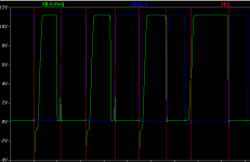
I have to disagree here. UcD400 uses FMMT618/718 emitter follower pair to speed up the transitions. Looking at the gate waveform of the lower mosfet none of the claimed mysterious advances could be seen. It has fair amount of ringing at the plateau. In fact gate waveform looked so ordinary I did not even bother to trace down the whole scematic of the driver.
That of course does not mean that UcD does not perform good. But the gate driver is not anything out of this world.
Best regards,
Jaka Racman
"I was thinking of body diode reverse recovery, dv/dt limitations, due to the hard switching."
The body diode reverse recovery is not a limit if you use metal-semiconductor junction clamper diodes with the MOSFETs. I think the UcD uses discrete drivers only because of the short propagation and the "simplicity". 😱 But that is a sub-optimal method in the light of transition time. The fast transitions would cause current spikes under the body diode recovery.
The body diode reverse recovery is not a limit if you use metal-semiconductor junction clamper diodes with the MOSFETs. I think the UcD uses discrete drivers only because of the short propagation and the "simplicity". 😱 But that is a sub-optimal method in the light of transition time. The fast transitions would cause current spikes under the body diode recovery.
Gyula said:The body diode reverse recovery is not a limit if you use metal-semiconductor junction clamper diodes with the MOSFETs. I think the UcD uses discrete drivers only because of the short propagation and the "simplicity". 😱 But that is a sub-optimal method in the light of transition time. The fast transitions would cause current spikes under the body diode recovery.
Yep, current spikes which can easily lead to breakdown and certainly high EMI. I don't think you can simply rely on a // diode, best to turn it right off, better yet if you need to switch that fast go with soft switching and dont' worry about it at all.
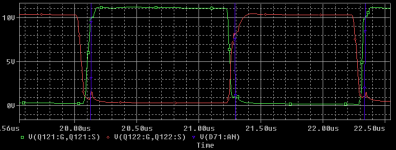
Jaka, good to know there's still room for improvement.. but it does seem like a neat idea. I haven't been able to get simulation waveforms ideal either, but it demonstrates the idea I guess.
Oh and thanks for the info, I am scopeless after all. It's still interesting to compare these waveforms to those of the much more complex rendition found in this thread.
Attachments
Hi Chris,
at the current time I have loaned my UcD 400 to the friend, second, modules are mounted in an old Grandson of Ampzilla case in a most awkward position, so it would be PITA to dismantle them, third I would have to catch some spare time at my job to measure them, so don't hold your breath I will do that any time soon. Probably not in 6 months time.
I also think that it would be pointless to argue about gate waveforms in a perfectly good working amplifier.
Best regards,
Jaka Racman
"I don't think you can simply rely on a // diode, best to turn it right off, better yet if you need to switch that fast go with soft switching and dont' worry about it at all."
How would you turn right off a schottky or realize Class-D soft-switching?
How would you turn right off a schottky or realize Class-D soft-switching?
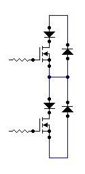
yep that's how you turn off the body diode. Saves me a screenshot.
Jaka Racman was kind enough to show a circuit that employs one form of soft switching in class D not long ago. I don't have the link.
Jaka Racman was kind enough to show a circuit that employs one form of soft switching in class D not long ago. I don't have the link.
What's this?: "yep that's how you turn off the body diode. Saves me a screenshot."
Yes. I am coruios about that soft switching link.. 😎
Yes. I am coruios about that soft switching link.. 😎
Soft switching with limited di/dt during diode recovery is achievable by means of magnetic snubbers, altough that imposes a minimum duty cycle of two to ten times the recovery time of the diode in order to allow the snubber inductor to reset.
Also, fast turn-on is an absolutely undesirable feature, because the higher the turn on di/dt the higher the reverse peak current from diode recovery and the higher the EMI spike radiated. Values between 50A/us and 200A/us depending on the type of body or external diode are desirable. Only fast turn-off is desirable.
Also, fast turn-on is an absolutely undesirable feature, because the higher the turn on di/dt the higher the reverse peak current from diode recovery and the higher the EMI spike radiated. Values between 50A/us and 200A/us depending on the type of body or external diode are desirable. Only fast turn-off is desirable.
Eva said:Soft switching with limited di/dt during diode recovery is achievable by means of magnetic snubbers, altough that imposes a minimum duty cycle of two to ten times the recovery time of the diode in order to allow the snubber inductor to reset.
Also, fast turn-on is an absolutely undesirable feature, because the higher the turn on di/dt the higher the reverse peak current from diode recovery and the higher the EMI spike radiated. Values between 50A/us and 200A/us depending on the type of body or external diode are desirable. Only fast turn-off is desirable.
😀
Eva I've been looking for a good example of a magnetic snubber to no avial .... would have a good reference handy?
- Status
- Not open for further replies.
- Home
- Amplifiers
- Class D
- Mosfet driver IC's